
High-power device heat dissipation device and method

A technology of high-power devices and heat dissipation devices, which is applied to the heat dissipation of high-power devices on aerospace vehicles. In the field of aerospace, it can solve the problems that cannot meet the heat dissipation requirements of high-power devices, so as to prevent high-temperature failures, increase heat dissipation paths, and ensure normal working effect

Active Publication Date: 2020-04-03
BEIJING RES INST OF TELEMETRY +1
View PDF6 Cites 2 Cited by
  • Summary
  • Abstract
  • Description
  • Claims
  • Application Information

AI Technical Summary

Problems solved by technology

In the past, only relying on the contact heat dissipation method between the printed board and the aluminum frame can no longer meet the heat dissipation requirements of high-power devices.

Method used


Image

  • High-power device heat dissipation device and method
  • High-power device heat dissipation device and method

Examples


Embodiment 1

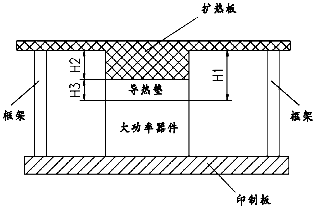
[0044] like figure 1 As shown, a heat dissipation method for a high-power device, the bottom of the high-power device is welded on the printed board through welding legs, the top of the high-power device is connected to the graphite heat spreader through the heat conduction pad, and the graphite heat spreader is fixedly connected to the frame , and the connection position between the frame and the graphite heat expansion plate has a heat conduction boss, the height of the heat conduction boss is 8-10mm, the graphite heat expansion plate is fixedly connected to the heat conduction boss of the frame through thermal grease, and the frame is fixedly connected to the cold plate; heat conduction The thickness of the pad is 0.4-0.5mm; there is a boss at the connection position between the graphite heat expansion plate and the heat conduction pad, and GD-414 glue is applied between the boss on the graphite heat spreader and the heat conduction pad.

[0045] First paste one side of the...

Embodiment 2

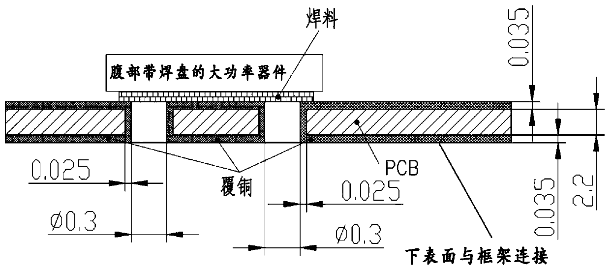
[0047] like figure 2 As shown, a heat dissipation method for high-power devices, the upper surface of the printed board is connected to the high-power device, the lower surface of the printed board is connected to the frame, and the connection between the upper surface of the printed board and the high-power device is coated with copper There are several through holes in the connecting part of the printed board and the high-power device. The inner surfaces of the several through holes are coated with a copper layer. The thickness of the copper layer is 0.025mm. The bottom of the high-power device is welded through the belly The disk is welded on the printed board; the diameter of the through hole is 0.2-0.3mm, and the number of the through hole is 20-30.

[0048] A method for dissipating heat from a high-power device, the steps of the method comprising:

[0049] (1) Process several through holes on the printed board;

[0050] (2) coating copper layer on the inner surface of...


PUM


Abstract

The invention relates to a high-power device heat dissipation device and method, belongs to the technical field of aerospace, and particularly relates to the technical field of heat dissipation of high-power devices on aerospace vehicles. The device and the method are matched with the layout of a printed board, a graphite heat diffusion plate is processed, and a boss is arranged in a position, corresponding to a high-power device on the printed board, on the heat diffusion plate; the printed board on which the components are welded is fixed on the frame; the distance between the top surface ofthe high-power device and the mounting surface of the heat diffusion plate is measured, the height of a heat dissipation boss of the graphite heat diffusion plate is machined according to the measured distance, when the heat conduction pad is mounted, heat conduction grease is additionally coated according to the distribution condition of the heat conduction grease on the high-power device, and heat conduction paths are increased for a heat dissipation device with a bonding pad at the belly.

Description

technical field [0001] The invention relates to a heat dissipation device and method for high-power devices, belonging to the technical field of aerospace, in particular to the technical field of heat dissipation for high-power devices on aerospace vehicles, where a high-power device means that the power of the device is not less than 5W. Background technique [0002] Excessive temperature rise of high-power devices is a problem often encountered in the field of engineering technology. As the size of the electronic equipment inside the aerospace vehicle becomes smaller and the power of the device is higher and higher, the heat dissipation of high-power devices has become a difficult point in product design. The previous method of only relying on the contact heat dissipation between the printed board and the aluminum frame can no longer meet the heat dissipation requirements of high-power devices. Contents of the invention [0003] When the technology of the present invent...

Claims


Application Information

Patent Timeline
Patent Type & Authority Applications(China)
IPC IPC(8): H01L23/373H01L23/367
CPCH01L23/367H01L23/373
Inventor 崔冠宇王宇郭益
Owner BEIJING RES INST OF TELEMETRY
Learn More