Oil cylinder part machining equipment

A technology of parts processing and oil cylinder, which is applied in the field of oil cylinder parts processing equipment, can solve the problems of high labor intensity, low drilling efficiency, and drilling errors, etc., and achieve the effect of convenient drilling and good fixing effect

Inactive Publication Date: 2020-04-07
嘉兴尚乐机电股份有限公司
View PDF7 Cites 2 Cited by
  • Summary
  • Abstract
  • Description
  • Claims
  • Application Information

AI Technical Summary

Problems solved by technology

[0003] Oil cylinder parts need to be drilled during the processing process, but the existing drilling machine for oil cylinder parts uses a punching machine, and then artificially applies pressure and uses the punching machine to punch holes, which is prone to large errors in punching. At the same time, the drilling efficiency is low and the labor intensity is high

Method used


Image

  • Oil cylinder part machining equipment
  • Oil cylinder part machining equipment
  • Oil cylinder part machining equipment

Examples


Embodiment

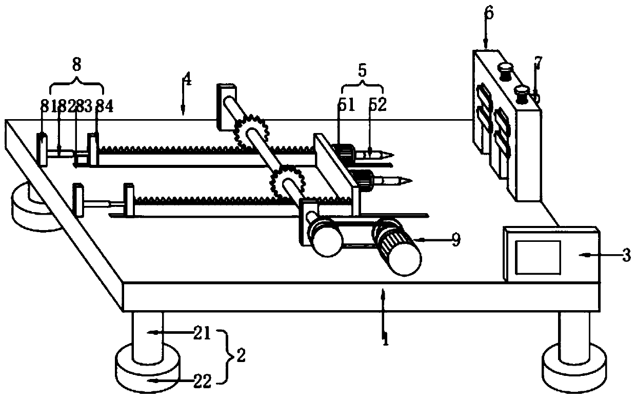
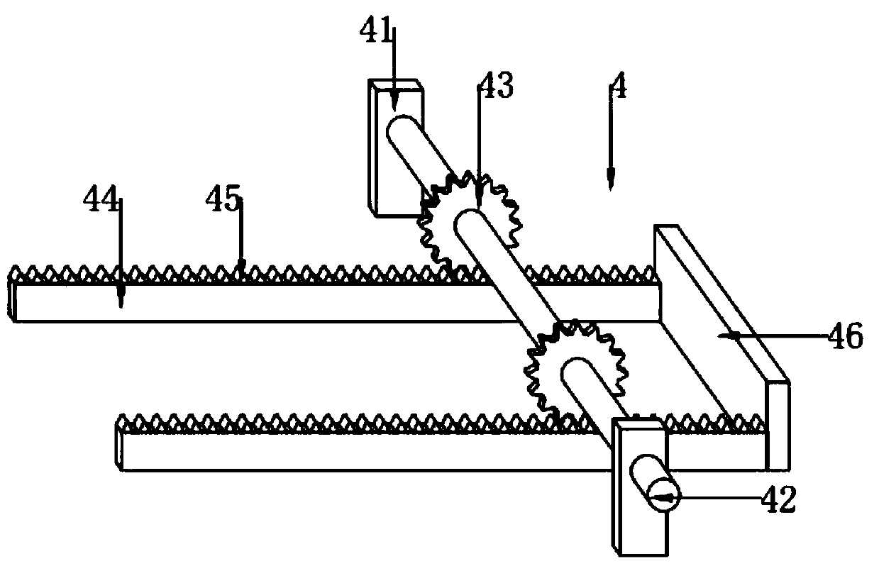
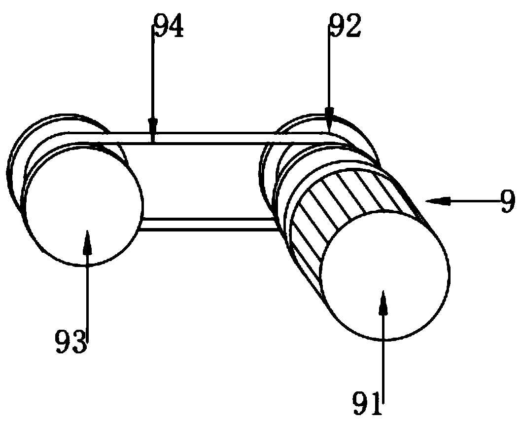
[0037] combine figure 1As shown, an oil cylinder part processing equipment includes a base 1 and a PLC controller 3, the PLC controller 3 is fixed on the upper end of the base 1, and the upper end of the base 1 is provided with a moving mechanism 4, a fixing mechanism 6 and a driving mechanism 9 , the driving mechanism 9 is connected with the moving mechanism 4 to drive the moving mechanism 4 to slide left and right, the fixing mechanism 6 is located on the right side of the moving mechanism 4, and the moving mechanism 4 is used to fix the oil cylinder parts to be processed, and the right side of the moving mechanism 4 is provided with a drilling hole Mechanism 5, drilling mechanism 5 comprises common motor 51 and drill bit 52, and common motor 51 is provided with two, and two common motors 51 are installed on the right side of moving mechanism 4, and drill bit 52 is provided with two, and two drill bits 52 They are respectively fixed at the output ends of two ordinary motors ...


PUM


Abstract

The invention discloses oil cylinder part machining equipment and belongs to the oil cylinder part machining technology. The equipment comprises a base and a PLC, wherein the PLC is fixed at an upperend of the base, a moving mechanism, a fixing mechanism and a driving mechanism are arranged at an upper end of the base, the driving mechanism is connected with the moving mechanism to drive the moving mechanism to slide left and right, the fixing mechanism is located on the right of the moving mechanism, the fixing mechanism is used for fixing a to-be-machined oil cylinder part, a drilling mechanism is arranged on the right side of the moving mechanism, the drilling mechanism comprises common motors and drill bits, the number of the common motors is two, the two common motors are installed on the right side of the moving mechanism, the number of the drill bits is two, the two drill bits are fixed to output ends of the two common motors respectively, the moving mechanism pushes the drilling mechanism to achieve drilling, and the driving mechanism and the drilling mechanism are both electrically connected with the PLC. The equipment is advantaged in that the equipment is high in punching efficiency, low in manual labor intensity, free of manual punching and high in automation degree.

Description

technical field [0001] The invention relates to the processing technology of oil cylinder parts, more specifically, relates to a kind of processing equipment of oil cylinder parts. Background technique [0002] The hydraulic cylinder is a linear motion actuator whose output force is proportional to the effective area of ​​the piston and the pressure difference on both sides. Its function is to convert hydraulic energy into mechanical energy. The input of the hydraulic cylinder is the flow and pressure of the fluid, and the output is the speed and force of linear motion. The piston of the hydraulic cylinder can complete linear reciprocating motion, and the output linear displacement is limited. The hydraulic cylinder converts hydraulic energy into reciprocating linear motion The energy conversion device of mechanical energy. The hydraulic cylinder is basically composed of cylinder barrel and cylinder head, piston and piston rod, sealing device, buffer device and exhaust devic...

Claims


Application Information

Patent Timeline
Patent Type & Authority Applications(China)
IPC IPC(8): B23B39/16B23B41/00B23B47/00B23Q5/38
CPCB23B39/161B23B41/00B23B47/00B23Q5/385
Inventor 李永涛蒋文明
Owner 嘉兴尚乐机电股份有限公司
Why Eureka
Try Eureka