Eureka AIR delivers breakthrough ideas for toughest innovation challenges, trusted by R&D personnel around the world.

Improved charging pile for new energy automobile

A new energy vehicle, an improved technology, applied in electric vehicle charging technology, charging stations, electric vehicles, etc., can solve the problems of burning out charging piles, large motor power consumption, general heat dissipation effect, etc., achieving good environmental protection, large Heat dissipation area, good heat dissipation effect

Pending Publication Date: 2020-04-07
商文辉
View PDF6 Cites 0 Cited by
  • Summary
  • Abstract
  • Description
  • Claims
  • Application Information

AI Technical Summary

Problems solved by technology

[0003] The overheating of the charging pile is prone to burn out, so it is necessary to dissipate heat inside the charging pile. The current heat dissipation method has a general heat dissipation effect. If a motor with a higher power is installed, the power consumption will be large

Method used


Image

  • Improved charging pile for new energy automobile
  • Improved charging pile for new energy automobile
  • Improved charging pile for new energy automobile

Examples


Embodiment 1

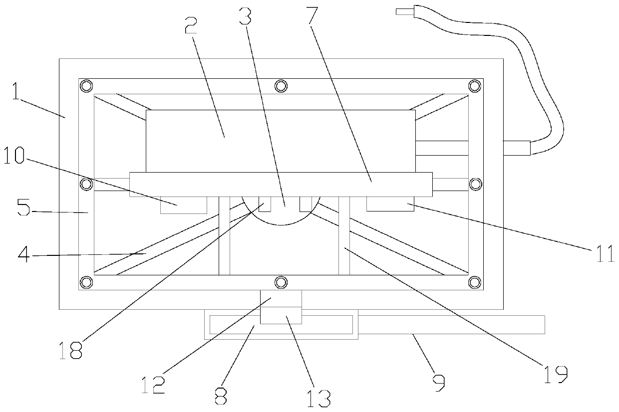
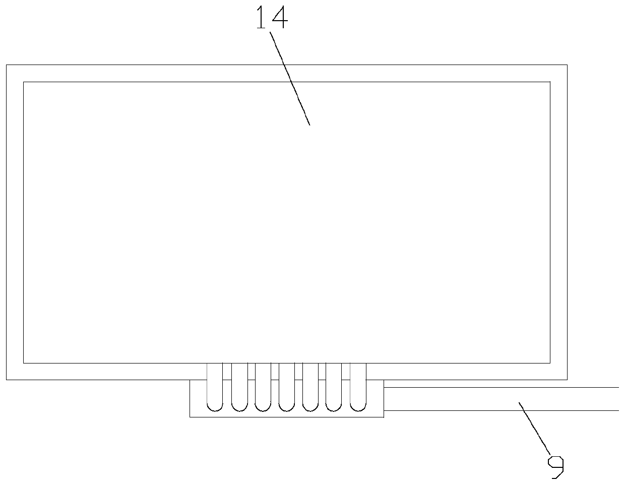
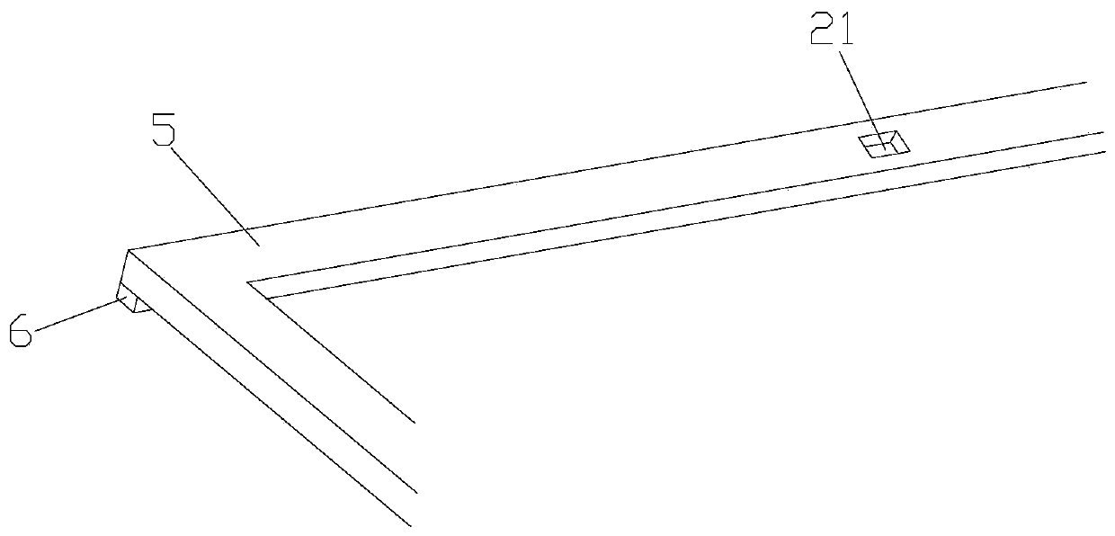
[0026] Such as Figure 1-4 As shown, an improved charging pile for new energy vehicles includes a heat-insulating box 1 and a charging module assembly 2, the bottom of the heat-insulating box 1 is provided with a mounting hole (not shown), and the inside of the mounting hole A connection water tank 3 is inserted, one end of the connection water tank 3 is located in the heat insulation box 1, the other end of the connection water tank 3 is located outside the heat insulation box 1, and the connection water tank 3 is located on one end outside the heat insulation box 1 A connecting pipe (not shown) for connecting to the buried tap water pipe is provided, and one end of the connecting water tank 3 located in the heat insulation box 1 is provided with a heat dissipation water pipe 4, and the heat dissipation water pipe 4 communicates with the connecting water tank 3, The connecting water tank 3 is fixedly connected with the heat insulation box 1, and the heat insulation box 1 is p...

Embodiment 2

[0029] Such as Figure 1-4 As shown, an improved charging pile for new energy vehicles includes a heat-insulating box 1 and a charging module assembly 2, the bottom of the heat-insulating box 1 is provided with a mounting hole (not shown), and the inside of the mounting hole A connection water tank 3 is inserted, one end of the connection water tank 3 is located in the heat insulation box 1, the other end of the connection water tank 3 is located outside the heat insulation box 1, and the connection water tank 3 is located on one end outside the heat insulation box 1 A connecting pipe (not shown) for connecting to the buried tap water pipe is provided, and one end of the connecting water tank 3 located in the heat insulation box 1 is provided with a heat dissipation water pipe 4, and the heat dissipation water pipe 4 communicates with the connecting water tank 3, The connecting water tank 3 is fixedly connected with the heat insulation box 1, and the heat insulation box 1 is p...


PUM


Abstract

The invention discloses an improved charging pile for a new energy automobile. The improved charging pile comprises a heat insulation box body and a charging module assembly, a mounting hole is formedin the bottom surface of the heat insulation box body; a connecting water tank is inserted into the mounting hole; a connecting pipe connected with a buried tap water pipe is arranged at the end, located outside the heat insulation box body, of the connecting water tank; a heat dissipation water pipe is arranged at one end, positioned in the heat insulation box body, of the connecting water tank;the connecting water tank is fixedly connected with the heat insulation box body; cooling fins are arranged in the heat insulation box body; the cooling fins are arranged in a square shapes; penetrating holes matched with the heat dissipation water pipe are formed in the cooling fins; supporting protrusions are arranged at the four corners of each cooling fin; gaps are formed between the coolingfins through the supporting protrusions; an installation frame is arranged on the heat insulation box body; and the charging module assembly is fixedly connected with the installation frame. The improved charging pile for the new energy automobile has a good heat dissipation effect, and meanwhile, the energy consumption for heat dissipation is relatively low.

Description

technical field [0001] The invention relates to an improved charging pile for new energy vehicles. Background technique [0002] The function of the charging pile is similar to the refueling machine in the gas station. It can be fixed on the ground or wall, and installed in the parking lot or charging station of public buildings and residential areas. It can charge various types of electric vehicles according to different voltage levels. The input end of the charging pile is directly connected to the AC grid, and the output end is equipped with a charging plug for charging the electric vehicle. Charging piles generally provide two charging methods: conventional charging and fast charging. People can use a specific charging card to swipe the card on the human-computer interaction interface provided by the charging pile to perform corresponding charging methods, charging time, and cost data printing. The display screen of the charging pile can display data such as charging am...

Claims


Application Information

Patent Timeline
IPC IPC(8): B60L53/31B60L53/302
CPCB60L53/31B60L53/302Y02T10/70Y02T10/7072Y02T90/12
Inventor 不公告发明人
Owner 商文辉
Why Eureka
Eureka Blog
Learn More