Turbomachinery rotor system blade set inclination and spinning angle precise adjusting device

A technology of turbomachinery and adjustment device, applied in the directions of rotors, mechanical equipment, safety devices, etc., can solve the problems of self-excited vibration of units, fatigue fracture of blades, limited application occasions, etc., achieve accurate spin angle, and realize synchronous adjustment , the effect of broadening the scope of application

Pending Publication Date: 2020-04-07
HUNAN UNIV OF SCI & TECH
View PDF0 Cites 0 Cited by
  • Summary
  • Abstract
  • Description
  • Claims
  • Application Information

AI Technical Summary

Problems solved by technology

The strong nonlinear vibration of blades caused by heat-fluid-solid coupling conditions in a confined space has always restricted the development of turbomachinery with high parameters, large capacity, and intelligence. Cause major economic losses or even casualties, but the combination of small dynamic changes in the spin angles of rotor blades at the same stage or the small dynamic changes in the spin angles of different rotors (between compressors, gas turbines and power turbine rotors) is the most important It is an important factor for the vibration response and energy conversion efficiency of turbomachinery under the excitation of continuous non-stationary airflow. In addition, the axial tilt of the blade set under sudden external excitation is also one of the reasons for the vibration of the turbomachinery rotor system to exceed the limit, such as Without early diagnosis, it may also lead to the above serious consequences
Although the second, third and fourth methods can easily achieve the purpose of adjusting the blade angle, but directly using the motor as the power input method, it is impossible to achieve precise adjustment of the spin angle of the blade group and the combined adjustment of the spin angle of different rotor blade groups , and none of the above methods can realize the adjustment of the axial tilt of the blade group, and cannot effectively diagnose the failure of the vibration exceeding the limit due to the axial tilt of the blade group, resulting in limited application

Method used


Image

  • Turbomachinery rotor system blade set inclination and spinning angle precise adjusting device
  • Turbomachinery rotor system blade set inclination and spinning angle precise adjusting device

Examples


Embodiment Construction

[0019] The present invention will be further described below in conjunction with the accompanying drawings.

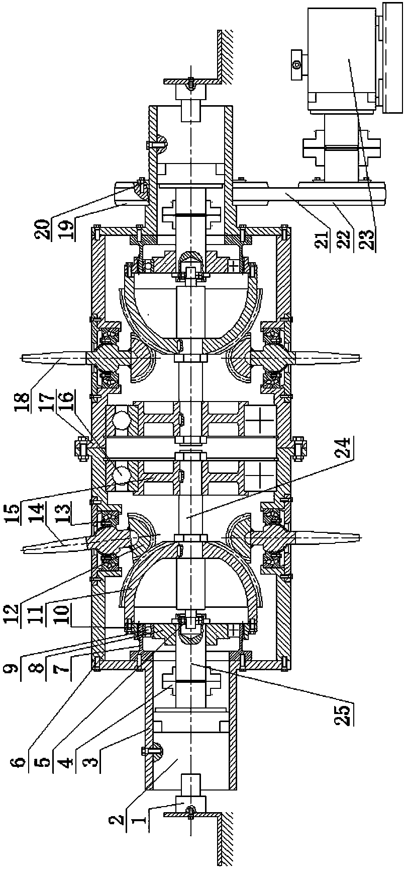
[0020] Such as figure 1 As shown, the present invention includes two brake motors, a rotor, a rotor drive mechanism and a blade shaft; the rotor includes a primary rotor 6 and a secondary rotor 17, the primary rotor 6 and the secondary rotor 17 are coaxial, and opposite One end is connected by bolts, and the rotor is a cylindrical structure. The two ends of the rotor are respectively provided with a motor connection seat 3, and a brake motor 2 is respectively provided in the two motor connection seats 3, and the two brake motors 2 are respectively electrically connected with two energized slip rings 1, and the energized slip rings 1 are electrically connected. Ring 1 supplies power. The output shafts of the two brake motors 2 are respectively connected to a reduction shaft 25 through a shaft coupling 4 . The reduction shaft 25 is provided with a rigid cam 8, and the...


PUM


Abstract

The invention discloses a turbomachinery rotor system blade set inclination and spinning angle precise adjusting device which comprises a brake motor, a rotor, a rotor driving mechanism and a blade shaft. At least one end of the rotor is provided with the brake motor; a rigid cam is arranged on a speed reducing shaft connected with the brake motor, a flexible gear is connected with a motor connecting base, an outer gear ring is arranged at the end, facing the rigid cam, of the flexible gear, and a flexible bearing is arranged between the outer gear ring and the rigid cam. The blade shaft is supported in the rotor through a bearing; an inner gear ring is arranged at the end part of the speed reduction hemispherical gear on the blade shaft and is meshed with an outer gear ring on the flexible gear; the rotor is provided with a plurality of blades, and the inner ends of the blades are provided with adjusting hemispherical gears meshed with the speed reduction hemispherical gears respectively. The invention provides the method of blade inclinability design, large reduction ratio design, hemispherical gear transmission, independent driving of a blade adjusting device and the like, and online and accurate adjustment of the self-rotating angle of the blade set in the inclination and high-speed operation process of the rotor system blade set can be realized.

Description

technical field [0001] The invention belongs to the field of turbomachinery, in particular to a device for precisely adjusting the inclination and spin angle of a blade group of a rotor system of a turbomachinery. Background technique [0002] Blades are the core components for energy conversion in turbomachinery rotor systems such as aero-engines, gas turbines, and air compressors. Their high-efficiency and stable operation under long-term, variable operating conditions, and wide speeds is of great significance to the safe service of the unit. The strong nonlinear vibration of blades caused by heat-fluid-solid coupling conditions in a confined space has always restricted the development of turbomachinery with high parameters, large capacity, and intelligence. Cause major economic losses or even casualties, but the combination of small dynamic changes in the spin angles of rotor blades at the same stage or the small dynamic changes in the spin angles of different rotors (bet...

Claims


Application Information

Patent Timeline
Patent Type & Authority Applications(China)
IPC IPC(8): F01D5/14F01D5/30F01D7/02F01D21/00F01D25/00
CPCF01D5/147F01D5/30F01D7/02F01D21/00F01D25/00
Inventor 李超宾光富周治港张亮姜璟珺李鸿光王维民
Owner HUNAN UNIV OF SCI & TECH
Why Eureka
Try Eureka