Floating oscillating water column type wave energy power generation device

An oscillating water column type, power generation device technology, applied in the directions of hydropower generation, ocean energy power generation, engine components, etc., can solve the problems of inconvenient disassembly and replacement, poor coordination, complex structure, etc., to prolong the service life and speed up the airflow. speed, the effect of reducing cable routing

Pending Publication Date: 2020-04-07
GUANGZHOU INST OF ENERGY CONVERSION - CHINESE ACAD OF SCI
View PDF1 Cites 2 Cited by
  • Summary
  • Abstract
  • Description
  • Claims
  • Application Information

AI Technical Summary

Problems solved by technology

This type of device is characterized by a single floating body, high material utilization rate, no collision problem, and the turbine and generator are located on the water surface without being affected by marine organisms. Inconvenient issues, resulting in poor compatibility with small offshore installations such as buoys

Method used


Image

  • Floating oscillating water column type wave energy power generation device
  • Floating oscillating water column type wave energy power generation device

Examples


Embodiment 1

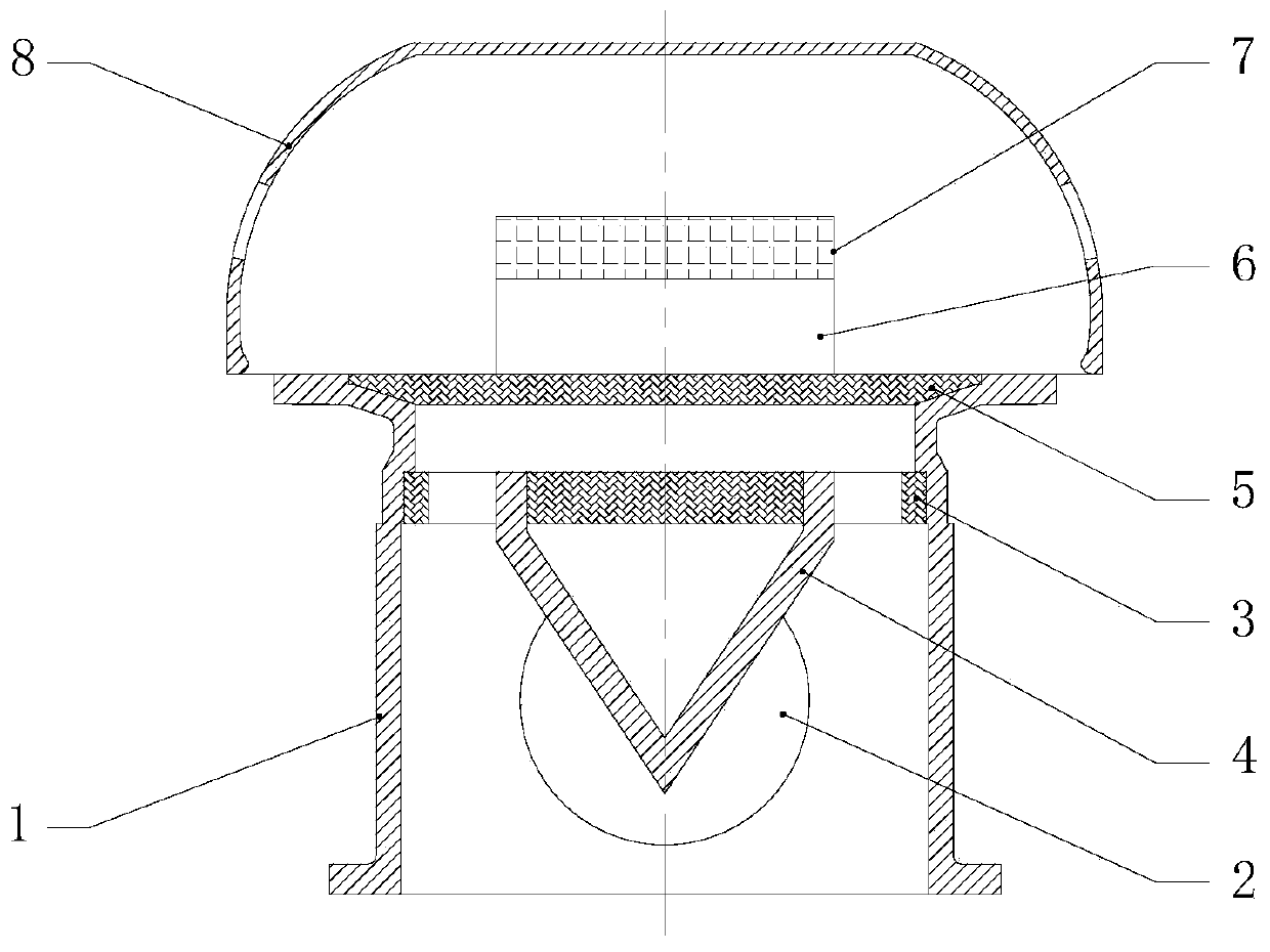
[0025] Such as figure 1 As shown, a floating oscillating water column type wave energy generating device includes a runner chamber 1 , a nozzle 3 , a diversion cone 4 , an impeller 5 , a generator 6 , a controller 7 and a protective cap 8 .

[0026] The runner chamber 1 is a cylindrical structure with a hollow interior, and a plurality of circular air valves 2 are arranged on the hub structure. Circular air valve 2 is made up of valve frame and valve, and valve can adopt soft material, for example, rubber sheet, is installed on the top of valve frame, and valve can only do opening and closing movement inwardly, is used in runner chamber-1. Air is replenished during pressing, and the specific opening and closing structure can adopt a conventional hinged joint method, which will not be repeated here.

[0027] The nozzle 3 is installed in the middle and upper part of the runner chamber-1, above the circular air valve 2, and is used to accelerate the air extruded into the runner ...

Embodiment 2

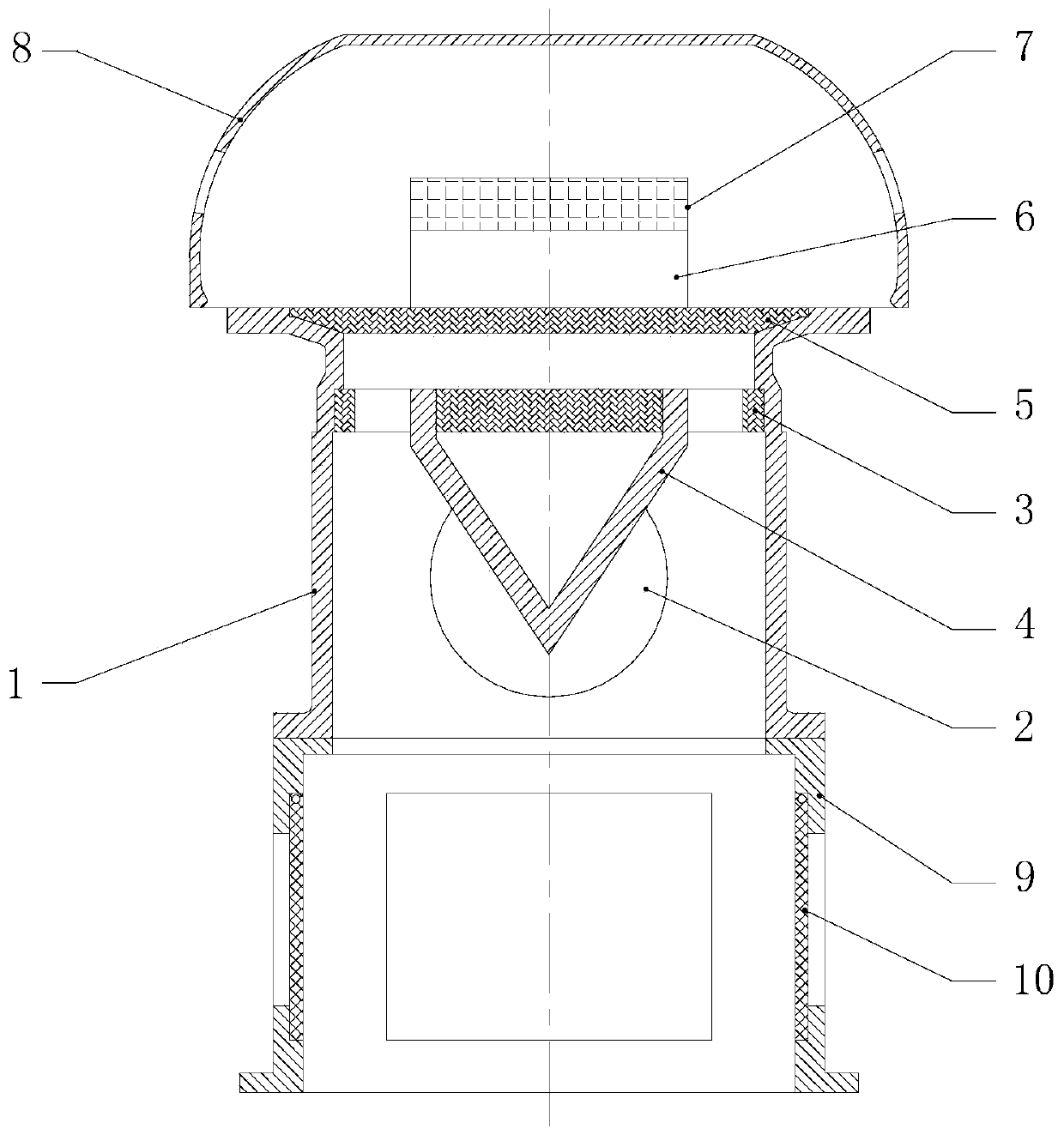
[0034] On the basis of embodiment 1, the runner chamber two 9 is added. Specifically, the runner chamber two 9 is installed directly below the runner chamber one 1, and the two are sealed by rubber. The second runner chamber 9 is a cuboid or cube structure, and the interior is hollow. There is a rectangular air valve 10 at the center of each vertical surface of the cube runner chamber 9; the rectangular air valve 10 is composed of a valve frame and a valve, and the valve adopts soft It is installed on the top of the valve frame, and the valve can only open and close inwards. The specific structure is the same as that of the circular air valve 2.

[0035] It should be noted that although Embodiment 1 uses a cylindrical runner chamber, it can be replaced with the square runner chamber of Embodiment 2 through a simple design. In this way, the floating oscillating water column type wave energy power generation The device can adopt different runner chambers according to different s...


PUM


Abstract

The invention discloses a floating oscillating water column type wave energy power generation device which comprises a runner chamber 1 and a protective cap, wherein a nozzle is arranged in the runnerchamber 1; a diversion cone is arranged below the nozzle and on the same central axis of the nozzle; the diversion cone is in a conical shape and has a downward tip end; an impeller is arranged abovethe nozzle and on the same central axis of the nozzle; a power generator is installed above the impeller and on the same axis of the impeller; the protective cap is installed at the top of the runnerchamber 1; and a gap for air circulation is formed between the edge of the protection cap and the edge of the runner chamber 1. The floating oscillating water column type wave energy power generationdevice uses the nozzle with the diversion cone structure. The diversion cone can guide the air flow direction, increase the air flow speed in the device, and simultaneously can slow down the upwellinof the waves in the runner chamber, protect the components in the device. Further, the protective cap effectively protect the components such as the power generator, a controller and the like in thedevice against the erosion of rainwater and seawater, thereby prolonging the service life of the device.

Description

technical field [0001] The invention relates to the technical field of marine renewable energy utilization, in particular to a floating oscillating water column type wave energy generating device utilizing wave energy to generate electricity. Background technique [0002] The ocean area accounts for about 71% of the earth's surface area, and there is abundant wave energy in the ocean. Wave energy is the most unstable energy in ocean energy, but as a clean renewable energy, it has a wide distribution and is easy to exploit and utilize on a large scale. The development and utilization of wave energy is mainly for wave energy power generation, desalination of seawater and providing power for other offshore equipment. The development and utilization of wave energy is an important direction in the field of renewable energy research in various countries. In particular, some coastal countries have invested a lot of money in researching various wave energy conversion and utilizatio...

Claims


Application Information

Patent Timeline
Patent Type & Authority Applications(China)
IPC IPC(8): F03B13/18F03B11/00
CPCF03B11/00F03B11/004F03B13/183Y02E10/20Y02E10/30
Inventor 梁贤光张亚群盛松伟叶寅
Owner GUANGZHOU INST OF ENERGY CONVERSION - CHINESE ACAD OF SCI
Why Eureka
Try Eureka