Steam flue gas heat exchange device by adopting three-stage heat exchange

A flue gas heat exchange and steam-water separation device technology, which is applied in the direction of indirect heat exchangers, heat exchanger types, heat exchange equipment, etc., can solve the problems of large volume, low economy, and large heat exchange area of ​​heat exchange devices , to achieve the effect of reducing heat transfer area, high economic benefit and improving heat transfer efficiency

Pending Publication Date: 2020-04-07
HANGZHOU NEW CENTURY ENERGY ENVIRONMENTAL PROTECTION ENG CO LTD
View PDF0 Cites 0 Cited by
  • Summary
  • Abstract
  • Description
  • Claims
  • Application Information

AI Technical Summary

Problems solved by technology

[0004] At present, the existing flue gas steam heat exchange device is composed of two-stage or one-stage heat exchange: the two-stage structure is generally: the first stage comes from the steam extraction of the turbine, and the low-pressure superheated steam from the turbine is used to transfer the flue gas from the original 100°C Heating from -110°C to 140°C-150°C, at this time, the low-pressure steam condenses into low-pressure water; the second stage comes from steam drum extraction, and the first-stage flue gas is further heated to 180°C-200°C, at this time, the high-pressure saturated steam condenses into high-pressure saturated water; or only the first-stage steam drum extracts steam for heat exchange to produce high-pressure saturated water, and the heat exchange system of this structure cannot make full use of the heat of saturated water , resulting in heat loss, and at the same time, in order to heat the flue gas to the required temperature, the required heat exchange area is large, the heat exchange device is large in size, and the economy is not high

Method used


Image

  • Steam flue gas heat exchange device by adopting three-stage heat exchange
  • Steam flue gas heat exchange device by adopting three-stage heat exchange

Examples


Embodiment Construction

[0018] The following will clearly and completely describe the technical solutions in the embodiments of the present invention with reference to the accompanying drawings in the embodiments of the present invention. Obviously, the described embodiments are only some, not all, embodiments of the present invention. Based on the embodiments of the present invention, all other embodiments obtained by persons of ordinary skill in the art without making creative efforts belong to the protection scope of the present invention.

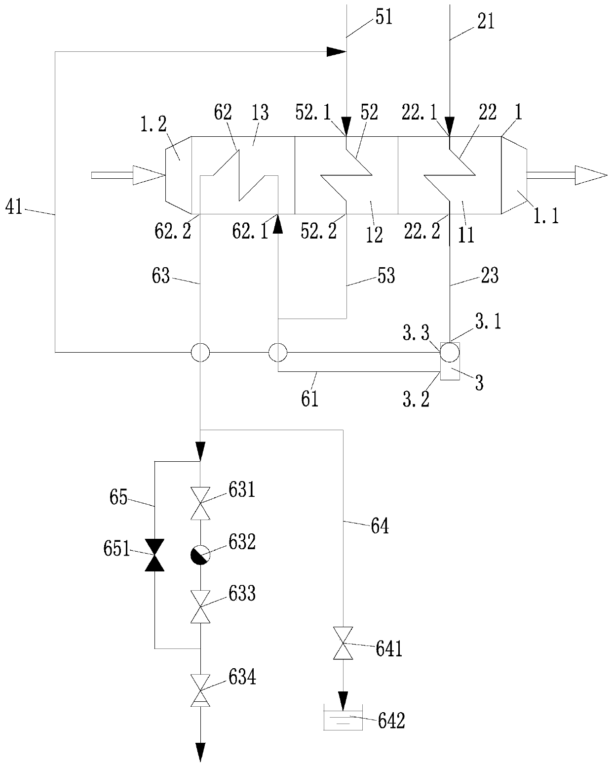
[0019] Such as figure 1 As shown, a steam flue gas heat exchange device adopting three-stage heat exchange includes a heat exchanger 1, a steam-water separation device 3, a heat exchange pipeline, a drain pipeline and a bypass pipeline.

[0020] The heat exchanger is a three-stage heat exchange structure, including a primary heat exchange tube box 13, a secondary heat exchange tube box 12 and a third stage heat exchange tube box 11 arranged along the flue gas ...


PUM


Abstract

The invention relates to the field of waste incineration, and aims to design a steam flue gas heat exchange device by adopting three-stage heat exchange. The device can heat flue gas to a proper temperature to meet the use condition of the flue gas, and can fully utilize the heat of a working medium. The device is characterized in that: the device comprises a heat exchanger, a steam-water separation device and a heat exchange pipeline, a first-stage heat exchange tube box, a second-stage heat exchange tube box and a third-stage heat exchange tube box which are arranged in the smoke flowing direction and communicate with one another in sequence are arranged in the heat exchanger. A flue gas inlet is formed in the first-stage heat exchange tube box, a flue gas outlet is formed in the third-stage heat exchange tube box, and a heat exchange tube is arranged in each heat exchange tube box; the heat exchange pipeline comprises a third-level high-pressure saturated steam leading-in pipe, a third-level high-pressure saturated water leading-out pipe, a second-level low-pressure superheated steam leading-in pipe, a second-level low-pressure saturated water leading-out pipe, a first-level low-pressure saturated water leading-out pipe, a first-level low-pressure water leading-out pipe and a second-level low-pressure saturated steam leading-out pipe.

Description

technical field [0001] The invention relates to the field of garbage incineration, in particular to a steam flue gas heat exchange device adopting three-stage heat exchange. Background technique [0002] At present, with the rapid development of cities, the problem of urban domestic waste is becoming more and more serious. How to realize the harmlessness, reduction and recycling of urban domestic waste has become a major problem facing the world. Among them, waste incineration has been widely used as a waste disposal method in China. At the same time, as the society pays more and more attention to environmental issues, the emission standards of pollutants produced by waste incineration are becoming more and more stringent. Require. [0003] The flue gas produced by waste incineration contains a certain amount of acid gas and nitrogen oxides. In order to meet the ultra-low requirements of acid gas emissions and NOx emissions, more and more processes are equipped with wet sc...

Claims


Application Information

Patent Timeline
IPC IPC(8): F23J15/08F28F21/08F28D7/08F28F1/12
CPCF23J15/08F28F21/084F28F21/082F28D7/082F28F1/12
Inventor 余军华罗誉娅沈华忠覃玲方涛
Owner HANGZHOU NEW CENTURY ENERGY ENVIRONMENTAL PROTECTION ENG CO LTD
Why Eureka
Try Eureka