Improved seismic source reverse time positioning method and computer readable storage medium

A positioning method and time-reverse technology, applied in the field of seismic exploration, can solve problems such as weak noise resistance and limited positioning accuracy, and achieve the effects of reducing background noise, improving positioning accuracy, and reducing positioning artifacts

Active Publication Date: 2020-04-07
CHINA PETROLEUM & CHEM CORP +1
View PDF8 Cites 1 Cited by
  • Summary
  • Abstract
  • Description
  • Claims
  • Application Information

AI Technical Summary

Problems solved by technology

However, there are various problems in conventional imaging conditions for seismic source reverse time location. For example, the maximum amplitude imaging condition is based on the characteristic that the energy is focused on the source position during the reverse time propagation process. This imaging condition is simple and effective, but it does not make full use of the reverse time delay. However, if the autocorrelation imaging condition is used, it makes full use of all the wave field values ​​at each moment in the reverse time continuation process, but the positioning results are in the There is strong amplitude noise near the geophone; for example, the multi-dimensio

Method used


Image

  • Improved seismic source reverse time positioning method and computer readable storage medium
  • Improved seismic source reverse time positioning method and computer readable storage medium
  • Improved seismic source reverse time positioning method and computer readable storage medium

Examples


Embodiment 1

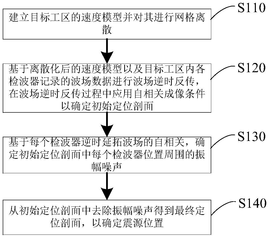
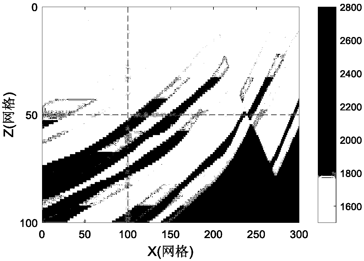
[0079] First, establish the velocity model of the target work area, and mesh the established velocity model (grid discretization)

[0080] Such as figure 2 Shown is the velocity model established in this embodiment. When the speed model is networked, the grid size is 301*101, the grid spacing is 4m, the sampling interval is 0.3ms, and the record length is 0.9s. And 301 geophones are arranged along the surface of the target work area, with a receiving distance of 4m.

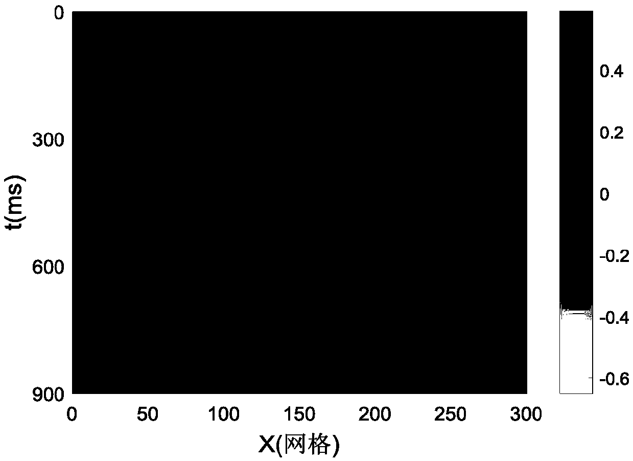
[0081] The source of the vibration is the Lake wavelet with a main frequency of 40Hz. Place the seismic source at the (100,50) grid for excitation, and the surface reception records are as follows image 3 As shown (in order to be close to reality, Gaussian random noise is added, SNR=0.5).

[0082] Afterwards, through the method of step S120 above, the initial positioning profile of the conventional autocorrelation imaging conditions obtained is as follows: Figure 4 As shown in , it can be seen that the lo...

Embodiment 2

[0090] In embodiment two, also adopt figure 1 The speed model shown is different in that the geophones in the target work area are distributed on the surface of the target work area with a large spacing (sparse distribution).

[0091] Specifically, in this embodiment, seven surface geophones with a distance of 200 m are used to perform reverse time positioning. The signal-to-noise ratio is 1, and the surface reception record is as follows Figure 9 shown.

[0092] In this example, Figure 10 It is the positioning profile of conventional autocorrelation imaging conditions. It can be seen that in the case of sparsely distributed geophones, conventional autocorrelation imaging conditions have strong amplitude noise around the geophone position, polluting the entire positioning profile.

[0093] Figure 11 In order to improve the positioning profile of autocorrelation imaging conditions, the strong amplitude noise of the shallow surface is eliminated, and the seismic source is...


PUM


Abstract

The invention discloses an improved seismic source reverse time positioning method and a computer readable storage medium, and the positioning method comprises the steps: building a speed model of a target work area, and carrying out the grid discretization of the speed model; performing wave field reverse time back propagation based on the discretized speed model and wave field data recorded by each detector in the target work area, and applying an autocorrelation imaging condition in the wave field reverse time back propagation process to determine an initial positioning profile; determiningamplitude noise around each detector position in the initial positioning profile based on the autocorrelation of the reverse time continuation wave field of each detector; and removing amplitude noise from the initial positioning profile to obtain a final positioning profile so as to determine the position of the seismic source. The positioning method can improve the seismic source positioning precision and reduce the positioning artifacts, and is especially suitable for the application scene of detector sparse distribution.

Description

technical field [0001] The invention belongs to the technical field of seismic exploration, and in particular relates to an improved seismic source reverse-time positioning method and a computer-readable storage medium. Background technique [0002] The reverse time location of the seismic source is a positioning method belonging to the wave equation category. It uses the time reversal invariance principle of the wave equation to realize the location of the seismic source. At the moment of excitation, the extended wave field is refocused on the source position, so as to realize the location of the source. [0003] The application of imaging conditions is an important link in the reverse time localization of seismic sources. The conventional imaging conditions for reverse time localization of seismic sources include maximum amplitude imaging conditions, autocorrelation imaging conditions, and multidimensional cross-correlation imaging conditions. However, there are various p...

Claims


Application Information

Patent Timeline
IPC IPC(8): G01V1/24
CPCG01V1/245
Inventor 雷朝阳朱童
Owner CHINA PETROLEUM & CHEM CORP
Why Eureka
Try Eureka