Combined current-limiting type direct-current circuit breaker for direct-current power grid

A technology for DC circuit breakers and DC power grids, which is applied in the direction of emergency protection circuit devices and electrical components, can solve the problems of economic benefits limiting the popularization and application of hybrid DC circuit breakers, achieve saving investment costs and floor space, and have obvious economic benefits , The effect of current limiting effect is obvious

Inactive Publication Date: 2020-04-07
SICHUAN UNIV
View PDF4 Cites 19 Cited by
  • Summary
  • Abstract
  • Description
  • Claims
  • Application Information

AI Technical Summary

Problems solved by technology

The hybrid DC circuit breaker has the advantages of small on-state loss, short breaking time, and arc-free breaking current. It is one of the most potential fault protection components, but the economic benefits limit the popularization and application of hybrid DC circuit breakers.

Method used


Image

  • Combined current-limiting type direct-current circuit breaker for direct-current power grid
  • Combined current-limiting type direct-current circuit breaker for direct-current power grid
  • Combined current-limiting type direct-current circuit breaker for direct-current power grid

Examples


Embodiment Construction

[0041] The technical scheme of the present invention is described in further detail below in conjunction with accompanying drawing, but protection scope of the present invention is not limited to the following description.

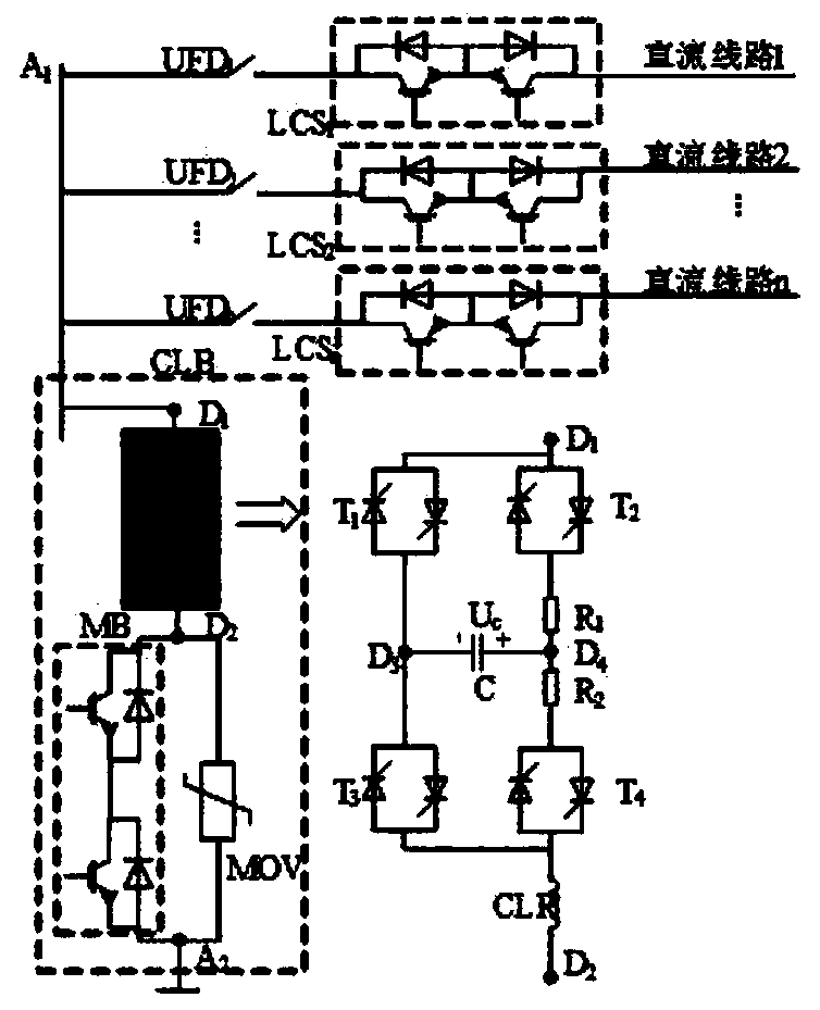
[0042] On the basis of existing research, the present invention proposes a combined current-limiting DC circuit breaker for DC power grids. The basic topology of the DC circuit breaker is as follows: figure 1 shown.

[0043] The DC circuit breaker is mainly composed of two parts: a current-carrying transfer branch and a current-limiting blocking branch CLB. The current-carrying transfer branch is composed of an ultra-fast mechanical switch UFD and a load commutation switch LCS in series, and the LCS is formed by a plurality of reverse-series IGBTs in series. The current-limiting blocking branch is composed of a current-limiting branch, a main circuit breaker branch MB, and an energy absorption branch. The current-limiting branch is composed of a charging ...


PUM


Abstract

The invention discloses a combined current-limiting direct-current circuit breaker for a direct-current power grid. The combined current-limiting direct-current circuit breaker comprises a current-carrying transfer branch and a current-limiting blocking branch; the current-carrying transfer branch is formed by connecting an ultra-fast mechanical switch and a load converter switch in series, one end of the current-carrying transfer branch is connected with a direct-current bus of a direct-current power grid, and the other end of the current-carrying transfer branch is connected to the direct-current power transmission line of the direct-current power grid in series; the current-limiting blocking branch comprises a current-limiting branch, a main circuit breaker branch and an energy absorption branch, one end of the main circuit breaker branch and one end of the energy absorption branch are connected in series with one end of the current-limiting branch after the main circuit breaker branch and the energy absorption branch are connected in parallel, and the other end of the current-limiting branch is connected to a potential point A1; and the other end of the main circuit breaker branch and the other end of the energy absorption branch are connected with a potential point A2 after the main circuit breaker branch and the energy absorption branch are connected in parallel. According to the invention, an expensive cutoff assembly can be separated from the circuit breaker for sharing, and the investment cost and the occupied area can be effectively reduced. A thyristor in the current-limiting blocking branch can share voltage to ground, and a charging resistor and a current-limiting inductor can effectively reduce the acceleration of a fault current and reduce the breaking current of the circuit breaker.

Description

technical field [0001] The invention relates to the field of power system automation, in particular to a combined current-limiting type DC circuit breaker for a DC power grid. Background technique [0002] With the increasing demand for new energy grid-connected consumption, high-voltage direct current grids, as an effective means of new energy grid-connected and high-power long-distance transmission, have attracted widespread attention. Among them, the modular multilevel converter based on voltage source commutation technology It has the advantages of PQ decoupling control, low harmonic level, and can supply power to passive systems. It has no troubles such as commutation failure and reactive power compensation, and has become the first choice to form a multi-terminal DC power grid. [0003] However, there are many problems to be solved urgently in the process of constructing DC power grid by MMC, such as fault protection. When the DC power grid fails, the capacitor of the...

Claims


Application Information

Patent Timeline
Patent Type & Authority Applications(China)
IPC IPC(8): H02H7/26
CPCH02H7/268
Inventor 王渝红凌楠曾琦曾昊傅云涛
Owner SICHUAN UNIV
Why Eureka
Try Eureka