
Assembly welding method for water-pumping and energy-storage socket ring

A technology of pumped storage and welding methods, applied in welding equipment, metal processing equipment, manufacturing tools, etc., can solve the problems of difficult control of welding deformation, poor welding quality, large amount of repair, etc., achieve controllable assembly size and improve product quality. Quality and the effect of improving assembly accuracy

Inactive Publication Date: 2020-04-10
HARBIN ELECTRIC MASCH CO LTD
View PDF5 Cites 2 Cited by
  • Summary
  • Abstract
  • Description
  • Claims
  • Application Information

AI Technical Summary

Problems solved by technology

[0002] The pumped storage power station uses the electric energy when the power load is low to pump water to the reservoir, and releases the water to the reservoir for power generation during the peak power load period. It can convert the excess electric energy when the grid load is low into high-value electric energy during the peak period of the grid; in recent years In the future, with the continuous development of my country's pumped storage technology, the installed capacity is getting bigger and bigger, and the water head is also getting higher; The welding work with the guide vane has brought great difficulties; in the past, the horizontal welding method was used, which was affected by the operating space and sightlines, the welding quality was poor, the UT effect of the flaw detection was not ideal, and the amount of repairs was large; the structure of the pile stop ring The rigidity is poor, and after being assembled to the seat ring one by one, the welding deformation is difficult to control, and the operable space is narrow, making welding difficult; therefore, the previous method of seat ring assembly and welding is no longer suitable for the manufacture of pumped storage seat rings at the present stage

Method used


Image

  • Assembly welding method for water-pumping and energy-storage socket ring
  • Assembly welding method for water-pumping and energy-storage socket ring

Examples


Embodiment Construction

[0018] A method for assembling and welding a pumped storage seat ring, comprising the following steps:

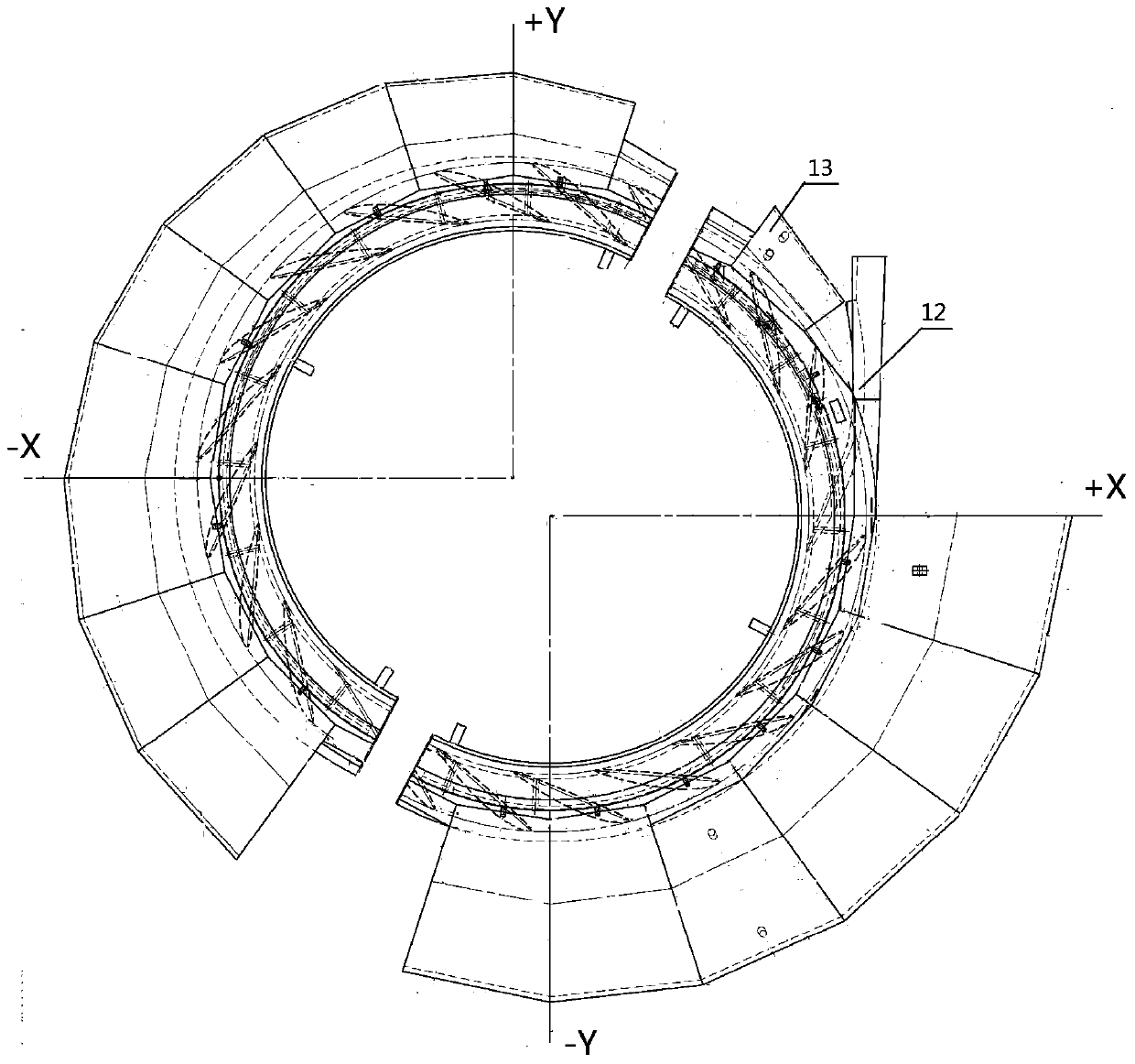
[0019] 1) In order to meet the transportation requirements, the pumped storage seat ring is divided into two parts at 180° for assembly and welding;

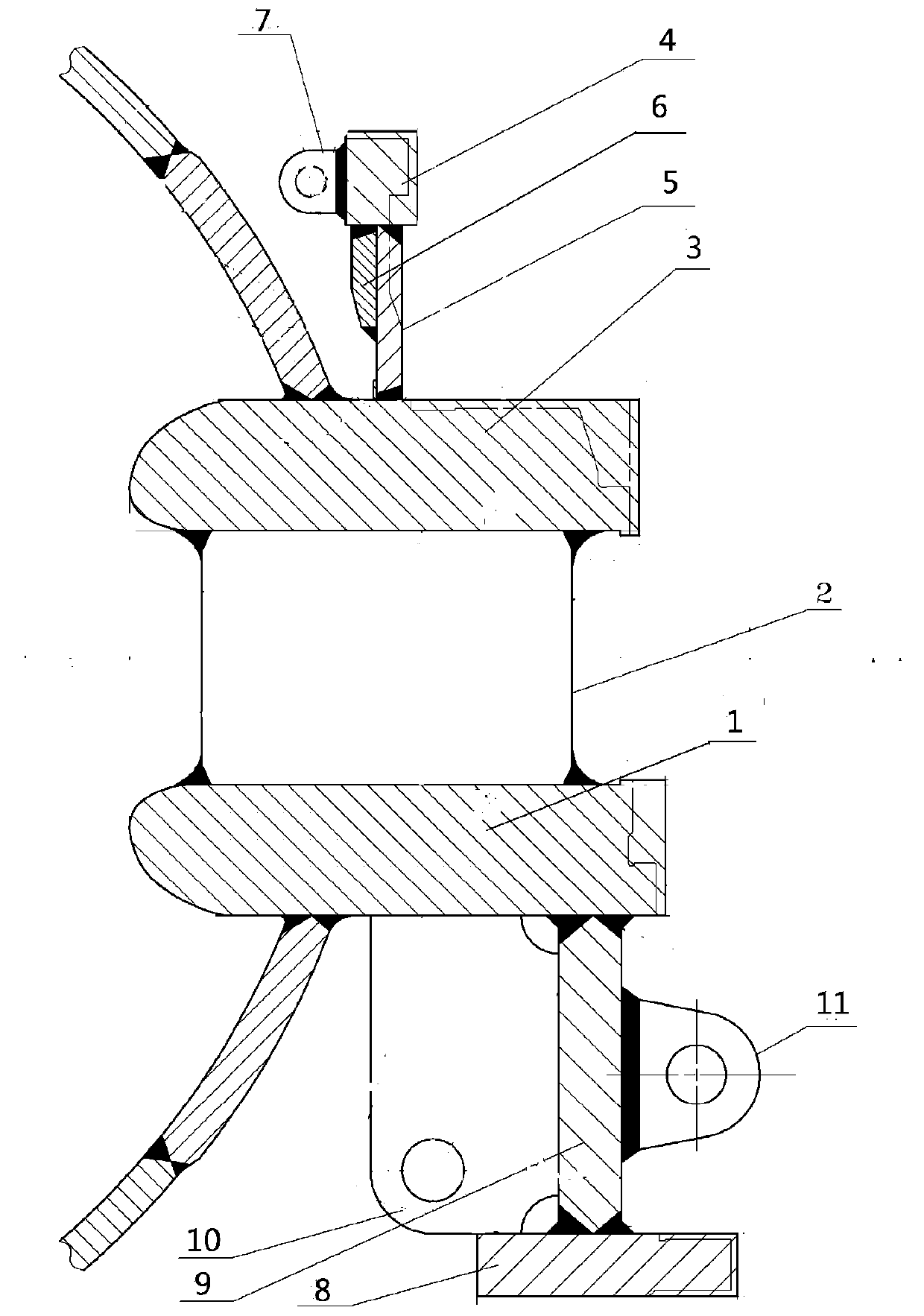
[0020] 2) Assemble the ring plate and the guide vane (such as figure 1 ): Hang the lower ring plate 1 on the platform and adjust the flatness to be no more than 1mm. The outer circle of the lower ring plate 1 is used as the reference, and the center of the circle is determined by combining the inner circle and the processing amount of the joint surface; draw the X, Y axis and the positioning line of the fixed guide vane 2 , and make a sample stamping mark, assemble the fixed guide vane 2 according to the positioning line to ensure that the verticality is not greater than 1mm; hoist the upper ring plate 3 to ensure that the assembly height of the flow surface is +8 ~ +10mm, and the coaxiality is not greater than 1mm; The valv...


PUM

PropertyMeasurementUnit
Verticalityaaaaaaaaaa

Abstract

The invention discloses an assembly welding method for a water-pumping and energy-storage socket ring. According to the structure characteristic of the water-pumping and energy-storage socket ring, aring plate, a guide vane, a check ring and a lower flange are laminated and welded separately, an occlusal rest, a transition segment and a volute are subjected to assembly welding, and the check part, the lower flange and the socket ring are subjected to assembly welding. A lamination mode is adopted for improving the structural strength to control welding deformation. After separate welding is completed, assembly is completed, part of welding deformation can be lowered, and accordingly the assembly precision is improved. The ring plate and the guide vane are subjected to vertical welding, vertical welding or climbing welding is adopted for replacing horizontal welding, the welding quality can be greatly improved, and the welding period is shortened. The product quality can be greatly improved. The assembly welding method has the advantages of being simple and clear, short in production period, low in cost and the like.

Description

Technical field: [0001] The invention relates to the field of pumped energy storage, in particular to a method for assembling and welding a pumped energy storage seat ring. Background technique: [0002] The pumped storage power station uses the electric energy when the power load is low to pump water to the reservoir, and releases the water to the reservoir for power generation during the peak power load period. It can convert the excess electric energy when the grid load is low into high-value electric energy during the peak period of the grid; in recent years In the future, with the continuous development of my country's pumped storage technology, the installed capacity is getting bigger and bigger, and the water head is also getting higher; The welding work with the guide vane has brought great difficulties; in the past, the horizontal welding method was used, which was affected by the operating space and sightlines, the welding quality was poor, the UT effect of the flaw ...

Claims


Application Information

Patent Timeline
IPC IPC(8): B23K31/02
CPCB23K31/02
Inventor 李凤超陈义胜王洪锦李明奎赵毓忠郑海涛任大勇许晓楠王余琛王一磊周晓龙
Owner HARBIN ELECTRIC MASCH CO LTD
Learn More