

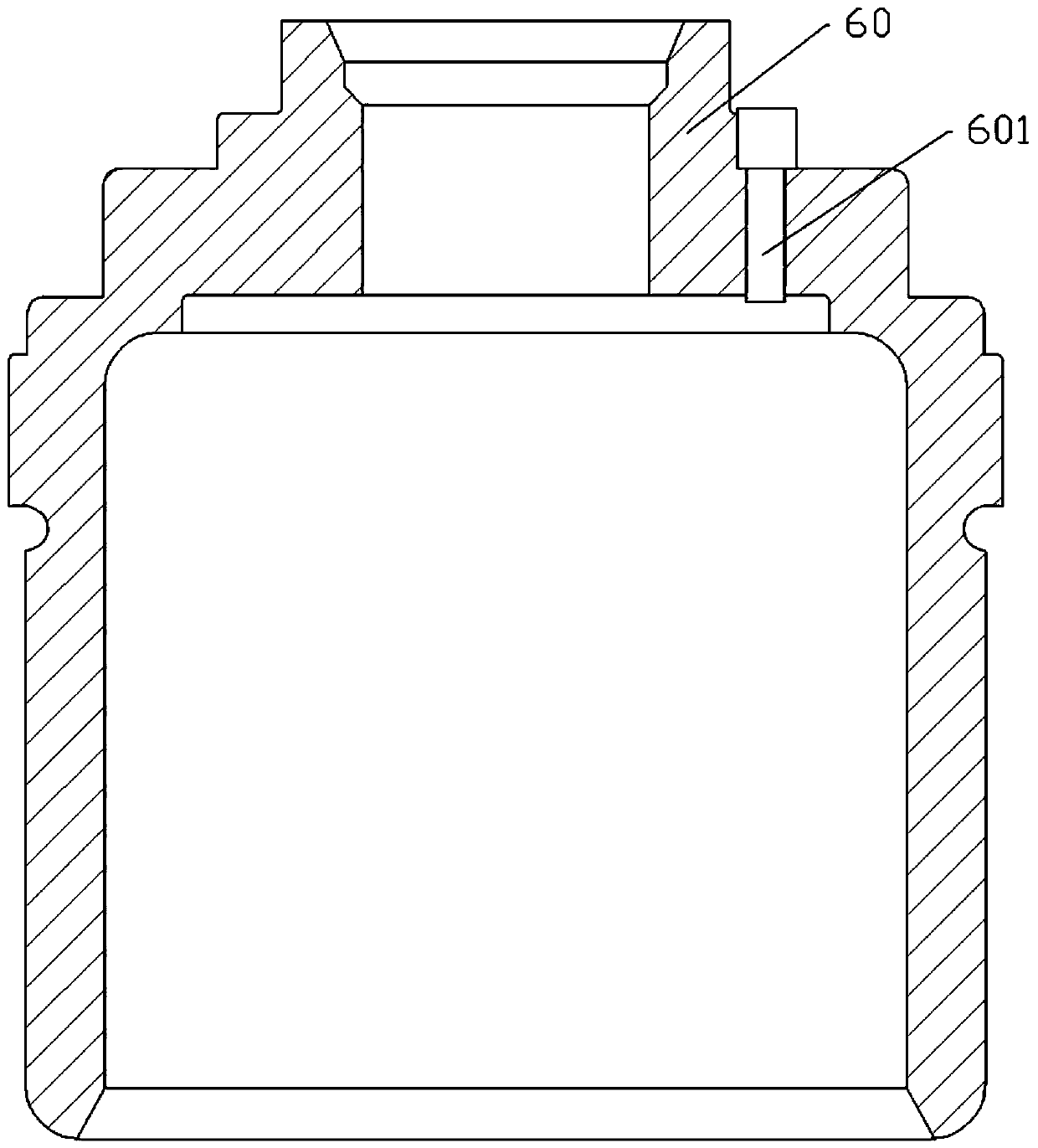
Clutch sleeve drilling and milling device
A clutch sleeve and barrel drilling technology, applied in the field of mechanical processing, can solve the problems of affecting the processing progress of the clutch sleeve 60 and the low efficiency of drilling and milling, and achieve the effects of quick and convenient pick-up process, improved synchronization and high efficiency
- Summary
- Abstract
- Description
- Claims
- Application Information
AI Technical Summary
Problems solved by technology
Method used
Image

Examples
Embodiment 1
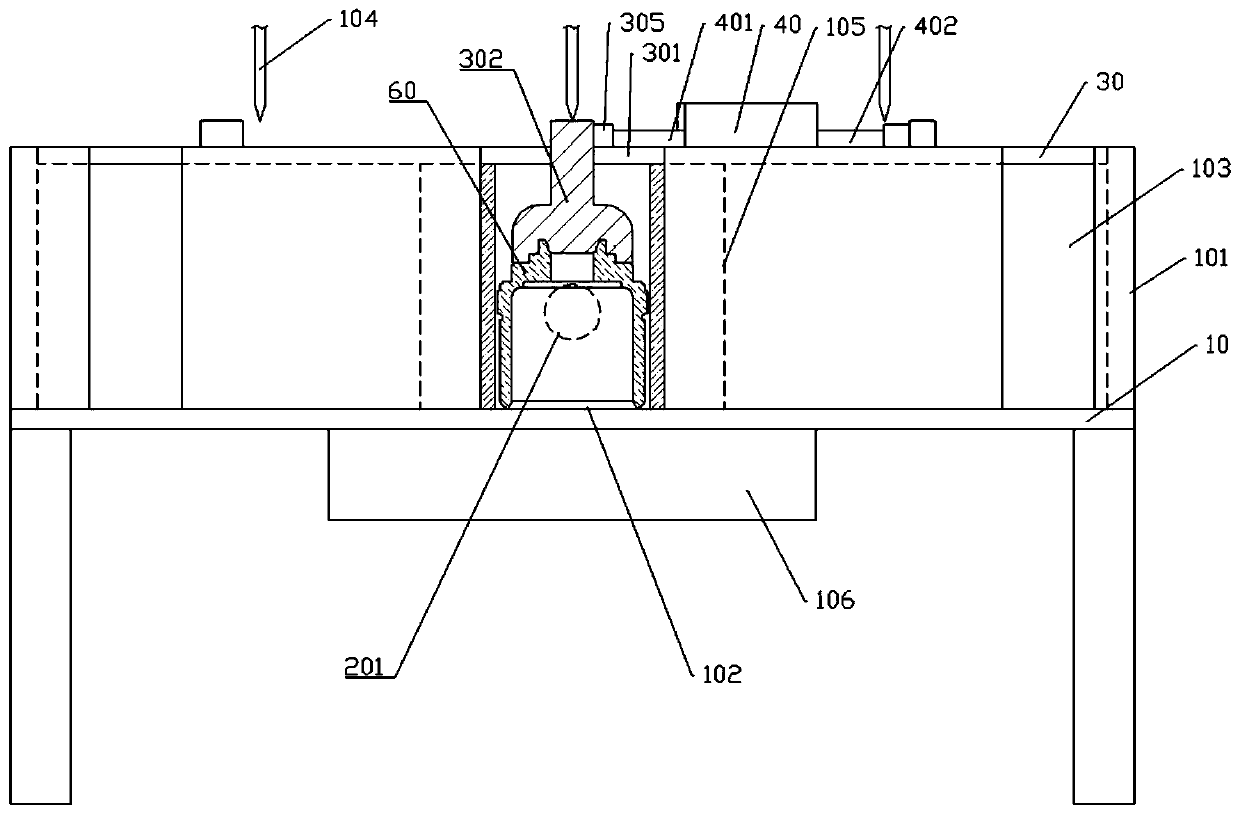
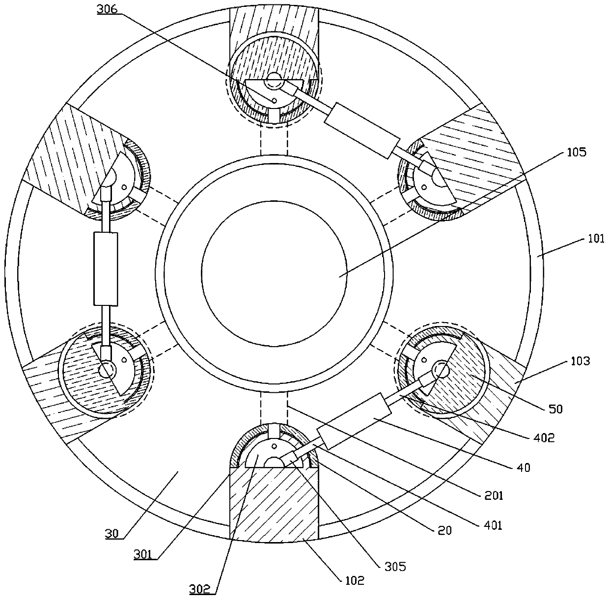
[0035] Embodiment 1 is basically as attached figure 2 , attached image 3 And attached Figure 4 Shown: the clutch sleeve drilling and milling device, including a circular processing table 10, three drill bits 104 that move vertically up and down, a turntable 105, a motor 106 that drives the turntable 105 to rotate, six drilling units and six clamping units , the motor 106 is welded on the lower surface of the processing table 10, the turntable 105 is coaxially rotated and installed on the upper surface of the processing table 10, and the lower end of the turntable 105 passes through the processing table 10 and is welded with the power output end of the motor 106, and the six drills The hole units and the six clamping units are uniformly arranged on the circumference of the turntable 105 .
[0036] Such as figure 2 As shown, the drilling unit includes a connecting rod 201 and a support plate 20 that can be in contact with the outer wall of the clutch sleeve 60, the connec...
Embodiment 2
[0045] The difference between embodiment 2 and embodiment 1 is that embodiment 2 is basically as attached Figure 5 And attached Image 6 As shown, the bottom of the processing table 10 is provided with a collection plate 50, a slide plate 501, a stage clip 502 and a string bar 503 vertically welded on the collection plate 50, the lower end of the string bar 503 is welded with the collection plate 50, and the upper end of the string bar 503 It is opposite to the drop-out hole; the slide plate 501 is provided with a slide hole for the string rod 503 to pass through, the inner wall of the slide hole is in sliding contact with the string rod 503, and the compression spring 502 is coaxially arranged on the string rod 503, and the lower end of the compression spring 502 is in contact with the string rod 503. The upper surface of the collecting plate 50 is welded, and the upper end of the stage clip 502 is welded with the lower surface of the slide plate 501 .
[0046] Such as Im...
PUM
 Abstract
Description
Claims
Application Information