Grinding device good in cooling effect for machining

A cooling effect, machine tool technology, applied in grinding/polishing safety devices, metal processing equipment, grinding/polishing equipment, etc., can solve the problems of cleaning the heat that cannot be dissipated, generating a large amount of heat, etc., to facilitate lifting and reducing The effect of friction

Inactive Publication Date: 2020-04-10
江苏伯能机床制造有限公司
View PDF6 Cites 1 Cited by
  • Summary
  • Abstract
  • Description
  • Claims
  • Application Information

AI Technical Summary

Problems solved by technology

A grinding device for processing magnetic valve spare parts in the above-mentioned patent has the following disadvantages: when the workpiece is ground, a large amount of heat will be generated, and the existing device cannot effectively clean up the emitted heat

Method used


Image

  • Grinding device good in cooling effect for machining
  • Grinding device good in cooling effect for machining
  • Grinding device good in cooling effect for machining

Examples


Embodiment 1

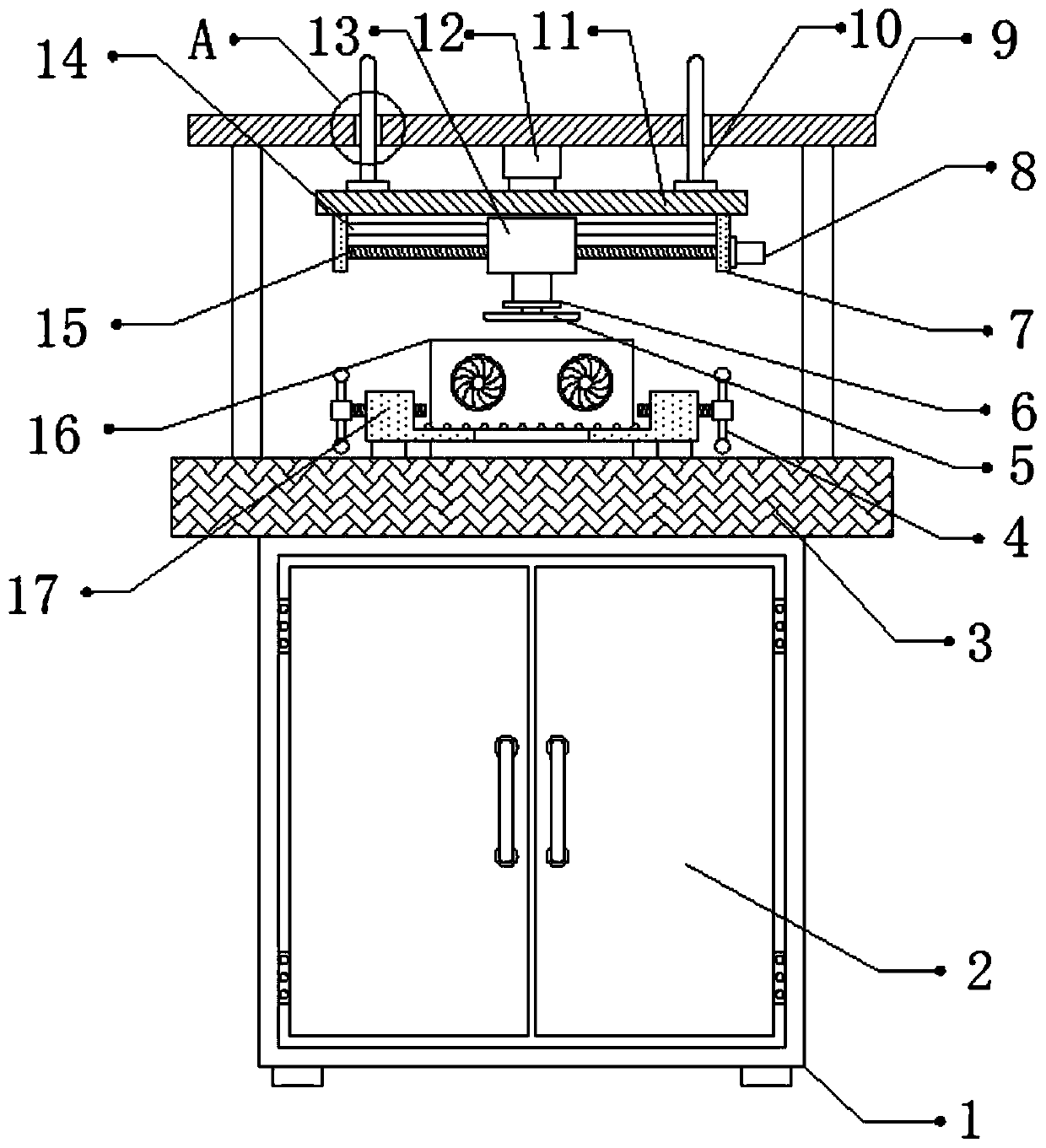
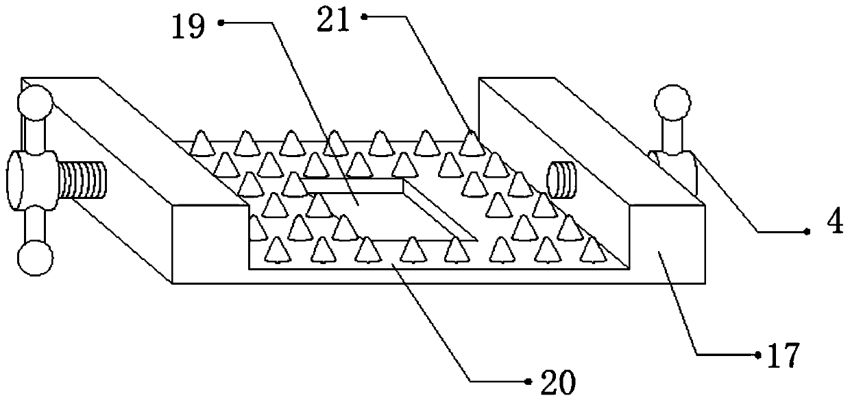
[0027] refer to Figure 1-3 , a grinding device with good cooling effect for machine tool processing, comprising a fixed seat 3, the top outer wall of the fixed seat 3 is connected with a fixed plate 17 by bolts, and the top outer wall of the fixed plate 17 is provided with a U-shaped groove 20, and the U-shaped groove The inner wall of the bottom of 20 is provided with a plurality of ribs 21 equidistantly distributed, the inner wall of the bottom of the U-shaped groove 20 is provided with an air vent 19, and one side of the outer wall of the top of the fixing seat 3 is connected with a cooling plate 16 by bolts, and the cooling plate 16 is a Both ends of the side outer wall are provided with cooling ports, and the inner walls of the two cooling ports are connected with cooling fans by bolts, and the two sides of the outer walls of the top of the fixing seat 3 are connected with fixed rods by bolts, and the top outer walls of the two fixed rods are connected to each other by bo...

Embodiment 2

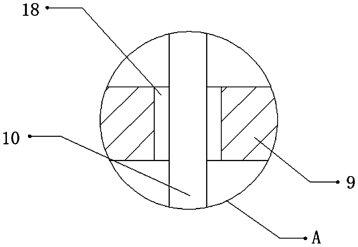
[0035] refer to Figure 4-5 , a grinding device with good cooling effect for machine tool processing. Compared with Embodiment 1, the inner walls of the two through holes 18 are provided with ball grooves, and the inner walls of the ball grooves are rollingly connected with balls 22, and the balls 22 The contact with the guide post 10 can reduce the frictional force between the guide post 10 and the through hole 18 to facilitate the lifting of the grinding disc 5 .

[0036]Working principle: when in use, place the workpiece to be ground inside the U-shaped groove 20, and by turning the threaded rod 4, the threaded rod 4 can clamp and fix the workpiece. The cutting disc 5 moves downward, and the first motor 6 will drive the grinding disc 5 to rotate, thereby grinding the workpiece. During this period, the second motor 8 drives the threaded screw 15 to rotate, so that the grinding disc 5 Move left and right, so as to carry out comprehensive grinding treatment on the workpiece, ...


PUM


Abstract

The invention discloses a grinding device good in cooling effect for machining. The grinding device comprises a fixed base. A fixed plate is fixed to the outer wall of the top of the fixed base. A U-shaped groove is formed in the outer wall of the top of the fixed plate. A plurality of protruding edges distributed at equal intervals are arranged on the inner wall of the bottom of the U-shaped groove. A vent hole is formed in the inner wall of the bottom of the U-shaped groove. A cooling plate is fixed to one side of the outer wall of the top of the fixed base. Cooling holes are formed in the two ends of the outer wall of one side of the cooling plate correspondingly. Cooling fans are fixed to the inner walls of the two cooling holes correspondingly. Fixed rods are fixed to the two sides ofthe outer wall of the top of the fixed base correspondingly. Top plates are fixed to the outer walls of the tops of the two fixed rods correspondingly. The grinding of workpieces can be prevented from being affected by a too high temperature, the shaking of workpieces caused by the shaking of the grinding device in work can be prevented, the machining offset of the workpieces caused by the left-right shaking of a grinding plate can be prevented, and the friction force between a guide column and a through hole can be reduced.

Description

technical field [0001] The invention relates to the technical field of machine tool processing, in particular to a grinding device with good cooling effect for machine tool processing. Background technique [0002] Grinding is a mechanical processing method for removing materials. It uses high-speed rotating grinding wheels and other abrasive tools to process the cutting process of the surface of the workpiece. Grinding belongs to finishing processing in mechanical processing, with less processing volume and high precision. [0003] After searching, the Chinese patent authorization number is CN207629796U, which discloses a grinding device for processing magnetic valve spare parts, including a grinding device body, and slide rails are symmetrically arranged on both sides of the inner upper side of the grinding device body, and The magnetic valve parts are placed on the sliding card between the two slide rails. The other side of the grinding disc is provided with a clamping pl...

Claims


Application Information

Patent Timeline
Patent Type & Authority Applications(China)
IPC IPC(8): B24B27/00B24B55/02
CPCB24B27/00B24B27/0092B24B55/02
Inventor 张海香邹海丰
Owner 江苏伯能机床制造有限公司
Why Eureka
Try Eureka