Briquetting machine for PVC plastic waste treatment
A technology of plastic waste and briquetting machine, which is applied in the fields of plastic recycling, mechanical material recycling, recycling technology, etc., can solve the problems of low efficiency, time-consuming and laborious, and increased transportation costs, and achieves guaranteed crushing effect, high efficiency, and simple operation. Effect
- Summary
- Abstract
- Description
- Claims
- Application Information
AI Technical Summary
Problems solved by technology
Method used
Image
Examples
Embodiment 1
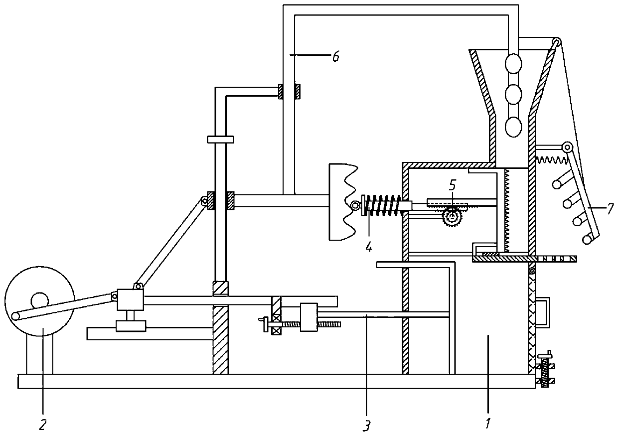
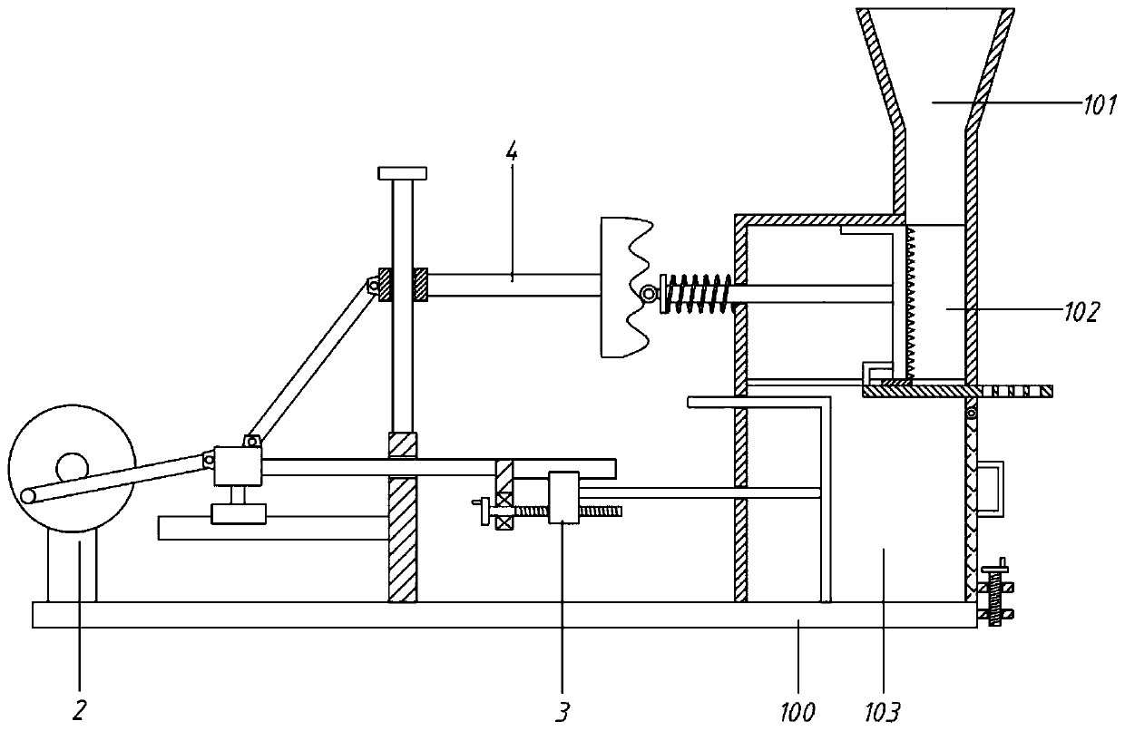
[0059] A briquetting machine for PVC plastic waste treatment, comprising a base 100, a housing 1, a drive assembly 2, a crushing assembly 5 and a compression assembly 3;
[0060] The housing 1 is arranged on the right side of the base 100, and is divided into a feeding hopper 101, a crushing chamber 102 and a compression chamber 103 from top to bottom; The partition 104 is fixed; the crushing chamber 102 is provided with the crushing assembly 4, and the compression chamber 103 is provided with the compression assembly 3; the driving assembly 2 is provided at the left part of the base 100, and the driving assembly 4 and the compression assembly 3 work together.
Embodiment 2
[0062] A briquetting machine for PVC plastic waste treatment, comprising a base 100, a housing 1, a drive assembly 2, a crushing assembly 5 and a compression assembly 3;
[0063] The housing 1 is arranged on the right side of the base 100, and is divided into a feeding hopper 101, a crushing chamber 102 and a compression chamber 103 from top to bottom; The partition 104 is fixed; the crushing chamber 102 is provided with the crushing assembly 4, and the compression chamber 103 is provided with the compression assembly 3; the driving assembly 2 is provided at the left part of the base 100, and the driving assembly 4 and the compression assembly 3 work together.
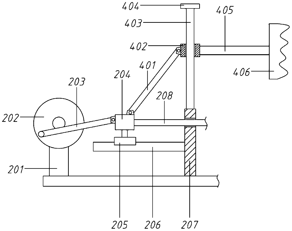
[0064] Wherein, the driving assembly 2 includes a motor base 201, a turntable 202, a No. 1 rod 203, a moving block 204, a No. 1 slider 205, a No. 1 slide rail 206, a No. 1 support plate 207 and a No. 2 rod 208;
[0065] The motor base 201 is fixed on the base 100, the top of the motor base 201 is equipped with a servo ...
Embodiment 3
[0080] On the basis of embodiment 2,
[0081] It also includes an enlargement assembly 5, which includes a No. 1 rack 501, a No. 1 installation rod 502, a pinion 503, a large gear 504, and a No. 2 rack 505;
[0082] The right end of the moving rod 409 is connected to a rack 501, and a pinion 503 is fitted under the rack 501. The pinion 503 is installed on the right end of the mounting rod 502, and the left end of the mounting rod 502 is fixed on the left side wall of the crushing chamber 102. The pinion 503 is coaxially connected with the bull gear 504, the bull gear 504 is equipped with the second rack 505, and the right end of the second rack 505 is connected with the second pressing plate 411; 505 protruding through holes.
[0083] Specifically, in this embodiment, the moving rod 409 is no longer directly connected to the second pressing plate 411 , but acts on the second pressing plate 411 through the amplifying component 5 . When the moving rod 409 moves, it drives the ...
PUM
 Abstract
Description
Claims
Application Information
 - R&D
- Intellectual Property
- Life Sciences
- Materials
- Tech Scout
- Unparalleled Data Quality
- Higher Quality Content
- 60% Fewer Hallucinations
Browse by: Latest US Patents, China's latest patents, Technical Efficacy Thesaurus, Application Domain, Technology Topic, Popular Technical Reports.
© 2025 PatSnap. All rights reserved.Legal|Privacy policy|Modern Slavery Act Transparency Statement|Sitemap|About US| Contact US: help@patsnap.com


