Electric infiltration phenomenon-based reversible micro-pump

An electrowetting and phenomenon technology, applied in the field of reversible micropumps, can solve the problems of low service life of piezoelectric pumps, single fluid flow direction control, and limited application range, etc., to achieve improved service life, strong reliability, and design simple effect

Active Publication Date: 2020-04-10
GUANGZHOU UNIVERSITY
View PDF5 Cites 6 Cited by
  • Summary
  • Abstract
  • Description
  • Claims
  • Application Information

AI Technical Summary

Problems solved by technology

Because the piezoelectric pump still has structures such as piezoelectric vibrators and cantilever beams, the service life of the piezoelectric pump is not high; moreover, the driving voltage of the piezoelectric pump is relatively high, and the control of the flow direction of the fluid is single, and there is a reverse flow on the microscopic level. Disadvantages, so it can only achieve macroscopic one-way net flow control, thus limiting the scope of its application

Method used


Image

  • Electric infiltration phenomenon-based reversible micro-pump
  • Electric infiltration phenomenon-based reversible micro-pump
  • Electric infiltration phenomenon-based reversible micro-pump

Examples


Embodiment 1

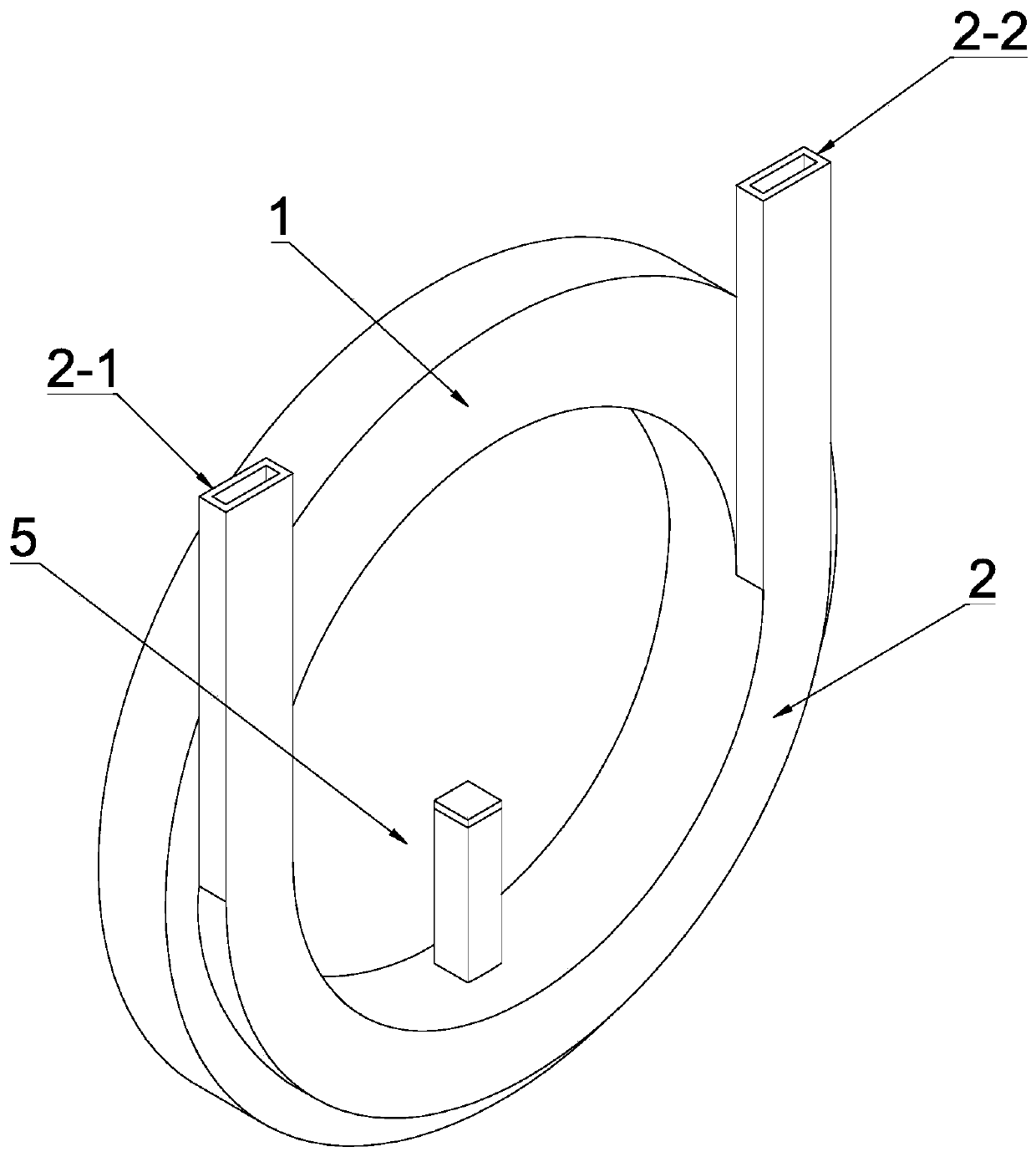
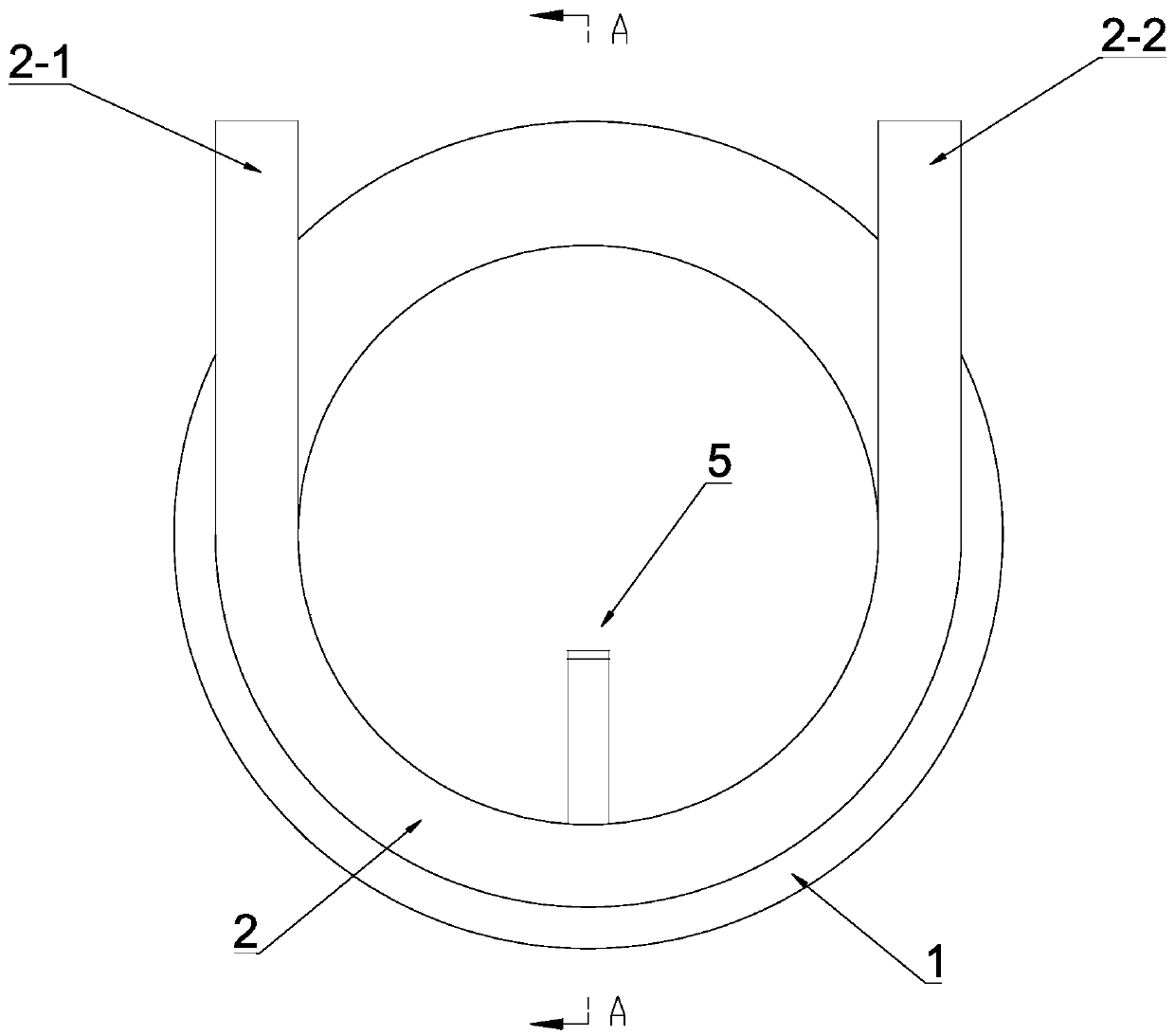
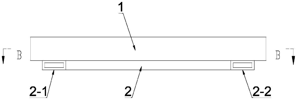
[0033] see Figure 1-Figure 7 , a reversible micropump based on the electrowetting phenomenon, characterized in that it includes an annular pump chamber 1, a liquid passage 2 arranged on the annular pump chamber 1; the annular pump chamber 1 and the liquid passage 2 There is a mesh 3 for connecting the annular pump chamber 1 and the liquid passage 2; the liquid passage 2 includes a first pump port 2-1 and a second Two pump ports 2-2; wherein, the annular pump chamber 1 is provided with a pump to pump the liquid in the annular pump chamber 1 to the first pump port 2-1 or the second pump port 2-2 The electrowetting power mechanism 4; wherein, the electrowetting power mechanism 4 includes the electrowetting liquid arranged in the annular pump chamber 1, nested on the side wall of the annular pump chamber 1 for driving the electrowetting The electrode array ring 4-1 where the liquid moves circularly along the annular pump chamber 1 and the dielectric hydrophobic material ring 4-2...

Embodiment 2

[0048] see Figure 8 , the other structure of this embodiment is the same as that of Embodiment 1, except that: the liquid passage 2 includes a first liquid passage 6 and a second liquid passage 7 respectively arranged at both ends of the annular pump chamber 1; The lower end of a liquid passage 6 communicates with the annular pump chamber 1 through the mesh 3, and the upper end is the first pump port 2-1; the lower end of the second liquid passage 7 communicates with the annular pump chamber through the mesh 3 1 connected, the upper end is the second pump port 2-2. With the above-mentioned structure, by changing the positive and negative poles of the DC power supply between the electrode array ring 4-1, the circular motion direction of the electrowetting liquid in the annular pump chamber 1 can be changed, thereby changing the motion direction of the pumped liquid, and micro Pumping and reversing functions of the pump.


PUM


Abstract

The invention discloses an electric infiltration phenomenon-based reversible micro-pump. The electric infiltration phenomenon-based reversible micro-pump comprises an annular pump cavity and a liquidchannel formed in the annular pump cavity; mesh holes are formed between the annular pump cavity and the liquid channel; the liquid channel comprises a first pump port and a second pump port, an electric infiltration power mechanism is arranged in the annular pump cavity, and the electric infiltration power mechanism comprises an electric infiltration liquid held in the annular pump cavity, an electrode array ring nested on the side wall of the annular pump cavity, and a dielectric hydrophobic material ring nested on the outer surface of the electrode array ring; a liquid replacing structure is arranged on the annular pump cavity; and the electric infiltration liquid and the pumped liquid are mutually insoluble. The micro-pump does not have a mechanical structure, is simple in design, andcan avoid mechanical wear produced in the using process of the micro-pump, so that the service life of the micro-pump is prolonged; and in addition, the micro-pump can control the pumping direction ofa fluid, and directional flowing of the pumped solution can be realized at both micro level and macro level.

Description

technical field [0001] The invention relates to the field of micropump devices, in particular to a reversible micropump based on the electrowetting phenomenon. Background technique [0002] The development and progress of microsystem technology has had a profound impact on many fields of society and life; with the rapid development of nanotechnology, micromachining technology, and material technology, microsystem technology has played an important role in MEMS, vascular robots, chemical analysis, The application potential in fields such as medical care and lab-on-a-chip is becoming more and more obvious, and the structural innovation and technical development of micropumps have become an important research direction in recent years. The micropump is an important executive device of the microelectromechanical system (MEMS), and the structure and performance of the micropump play a decisive role in the operation of the whole system. [0003] At present, there are various type...

Claims


Application Information

Patent Timeline
Patent Type & Authority Applications(China)
IPC IPC(8): F04B19/00
CPCF04B19/006
Inventor 江帆温锦锋陈美蓉沈健祝韬黄海涛黄浩翔
Owner GUANGZHOU UNIVERSITY
Why Eureka
Try Eureka