Piezoelectric shunt semi-passive control device and design method for vibration control of propulsion shafting

A technology of vibration control and design method, applied in the direction of propulsion transmission, transmission with synchronous propulsion components, mechanical vibration control, etc., can solve problems such as system complexity, and achieve the effect of reducing demand, small additional mass, and widening bandwidth

Active Publication Date: 2021-06-29
SHANGHAI JIAO TONG UNIV
View PDF5 Cites 0 Cited by
  • Summary
  • Abstract
  • Description
  • Claims
  • Application Information

AI Technical Summary

Problems solved by technology

However, the system includes measurement, control, and piezoelectric stack hydraulic micro-displacement amplifier actuators, etc., and the system is complex

Method used


Image

  • Piezoelectric shunt semi-passive control device and design method for vibration control of propulsion shafting
  • Piezoelectric shunt semi-passive control device and design method for vibration control of propulsion shafting
  • Piezoelectric shunt semi-passive control device and design method for vibration control of propulsion shafting

Examples


Embodiment 1

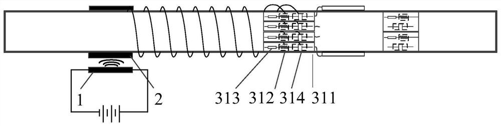
[0067] Such as figure 1 As shown, the power supply device adopts the induction telemetry power supply device.

[0068] The transmitting end (stationary end 1) is composed of a power supply, a power adapter, a power transmitter, and a power cord. The voltage of the transmitter is 40V DC (that is, the output voltage of the receiving end of the induction telemetry power supply). It can be supplied by batteries, or by inductive or mains power. Usually it can be obtained by inputting 220V AC power to the power adapter. The installation position of the power transmitter from the outer edge of the shaft system is related to the current size: 1000mA current distance is 5-10mm; 500mA current distance is 10-15mm; 250mA current distance is 15-20mm. The coil wound on the shaft is located in the middle of the front surface of the power transmitter probe.

[0069] The receiving end 2 is composed of a coil wound on the rotating shaft. After selecting a suitable installation position on ...

Embodiment 2

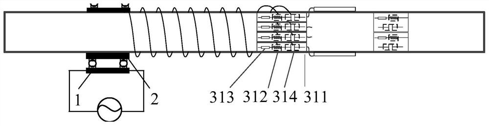
[0108] On the basis of the first embodiment, the power supply device is changed to a slip ring power supply device.

[0109] The stator (transmitter 1) of the slip ring power supply device is composed of an annular shell, a terminal, a conductive ring, a brush, and a shell fixing device. The rotor (receiving end 2) of the slip ring power supply device is composed of conductive rings and brushes; the rotor of the slip ring power supply device is fixed on the propulsion shafting through interference fit, and the stator of the slip ring power supply device is supported by precision bearings. The power supply unit can input voltage up to 500V.

[0110] The piezoelectric shunt circuit is fixed to the shaft and rotates with the shaft. First wrap the piezoelectric shunt circuit that rotates with the shaft on the shaft for 2 to 3 layers with adhesive tape to achieve a fixed effect, and finally use a hose clamp or hose clamp to hoop the piezoelectric shunt circuit and fix it on the ro...


PUM


Abstract

The present invention provides a piezoelectric shunt semi-passive control device and design method for the vibration control of the propulsion shaft system, comprising: a piezoelectric shunt circuit: connected to the propulsion shaft of the propulsion shaft system, and rotates with the propulsion shaft; power supply device: It includes a stationary end and a rotating end, the rotating end is connected to the propulsion shaft, rotates with the propulsion shaft, and is electrically connected with the piezoelectric shunt circuit, the stationary end is arranged on the periphery of the rotating end, through The swivel end supplies power to the piezoelectric shunt circuit. The invention adopts dynamic vibration absorption measures to effectively suppress the longitudinal and lateral vibrations of the propeller, has small additional mass, and has little influence on the misalignment of the shaft system.

Description

technical field [0001] The invention relates to the technical field of ship vibration reduction, in particular to a piezoelectric shunt semi-passive control device for controlling the longitudinal and transverse vibrations of a propulsion shafting and its design method and use method. Background technique [0002] There are prominent system natural frequency peaks in the low frequency range of the propulsion shafting, including the longitudinal and transverse bending vibration modes of the shafting system and the vibration mode of the propeller. Since the propeller broadband excitation force is large and will gradually decrease as the frequency increases, and the longitudinal broadband excitation force is 4 to 5 times that of the transverse broadband excitation force, the first-order longitudinal vibration mode and the first-order transverse bending vibration mode of the shafting The peak at the state is the most prominent. If these two peaks can be controlled, the vibratio...

Claims


Application Information

Patent Timeline
Patent Type & Authority Patents(China)
IPC IPC(8): F16F15/00G05D19/02B63H23/32
CPCB63H23/32B63H23/321B63H2023/325F16F15/002F16F2228/063F16F2230/18G05D19/02
Inventor 黄修长华宏星苏智伟黎丰郑智伟
Owner SHANGHAI JIAO TONG UNIV
Why Eureka
Try Eureka