Reducer gasket, reducer and method for determining thickness of reducer gasket

A reducer and gasket technology, which is applied to transmission parts, belts/chains/gears, mechanical equipment, etc., can solve the problems affecting the life of bearings and the performance of the whole machine, inconsistent bearing assembly height, and the same preload, etc., to achieve Solve the inclination problem of the main bearing system, ensure the thickness of the gasket is consistent, and improve the installation accuracy

Active Publication Date: 2020-04-10
格力电器(杭州)有限公司 +1
View PDF7 Cites 1 Cited by
  • Summary
  • Abstract
  • Description
  • Claims
  • Application Information

AI Technical Summary

Problems solved by technology

When applying preload to the bearing system, it is necessary to ensure that the rigid disk of the planetary carrier is in a state of fit in advance. However, due to the inconsistent assembly height of the currently used bearings, it is impossible to ensure that the preload of the bearing system in each reducer is the same, resulting in bearings Deviating from the best working life state, affecting the bearing life and overall machine performance
like figure 1 As shown, in order to solve the above-mentioned probl

Method used


Image

  • Reducer gasket, reducer and method for determining thickness of reducer gasket
  • Reducer gasket, reducer and method for determining thickness of reducer gasket
  • Reducer gasket, reducer and method for determining thickness of reducer gasket

Examples


Embodiment 2

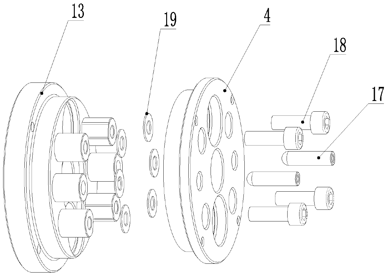
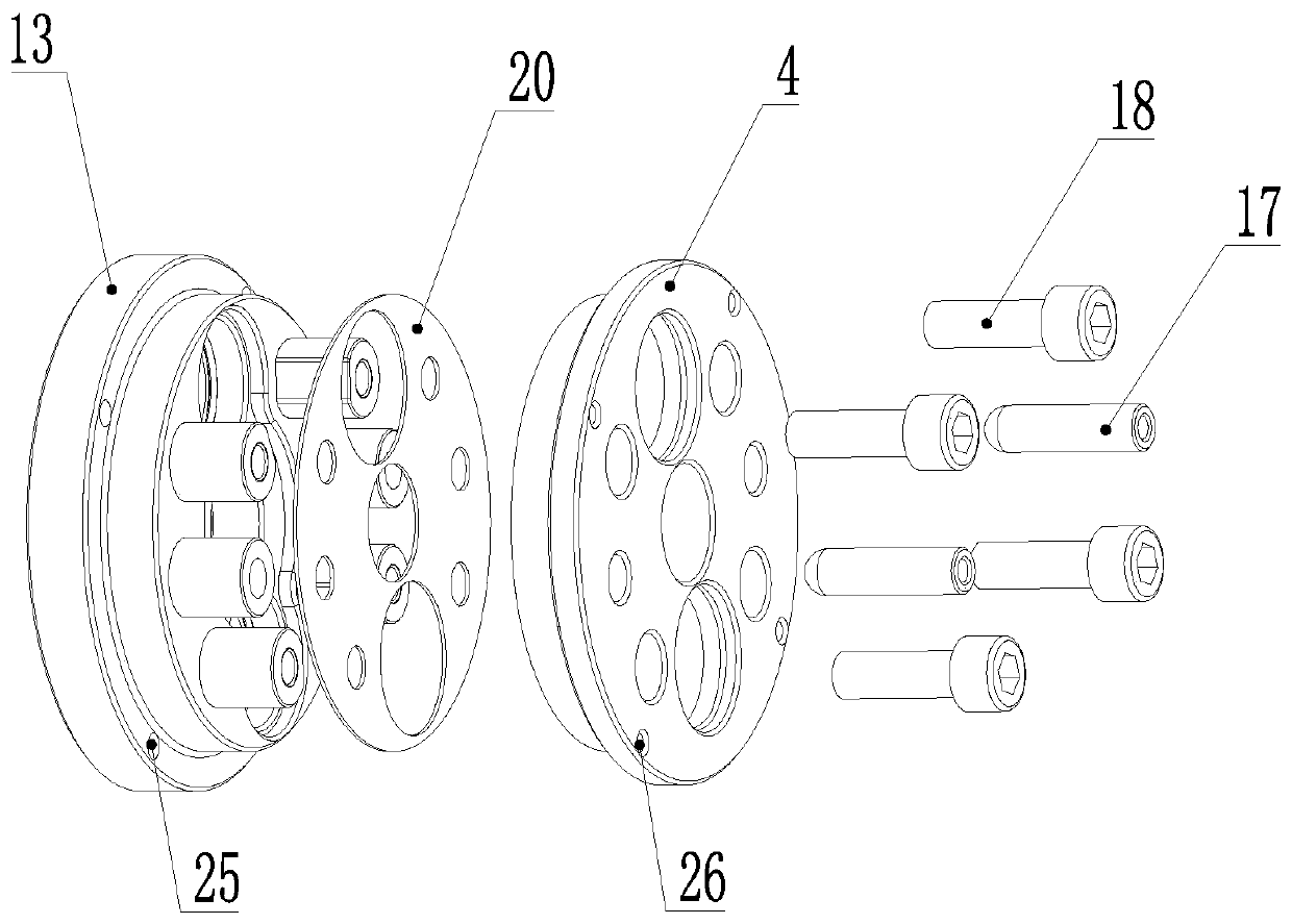
[0043] The difference between this embodiment and Embodiment 1 is that there are four first threaded through holes 25 and four second threaded through holes 26 , and they are evenly distributed on the circumference of the same diameter around the main shaft of the reducer. By setting such a ejection structure, it is convenient to disassemble the inner ring of the main bearing of the reducer accurately and completely, so as to prevent the inner ring from being damaged during the disassembly process, which is beneficial to repeated use.

Embodiment 3

[0045] The difference between this embodiment and Embodiment 1 lies in that: the chamfer 27 is arranged on one side of the large diameter of the pin hole 22 , corresponding to the rigid disc 4 . This can facilitate the positioning of the reducer spacer 6 and the rigid disk 4, so that the assembler can identify it, and it is beneficial to avoid assembly errors.


PUM


Abstract

The invention discloses a reducer gasket, a reducer and a method for determining the thickness of the reducer gasket, and particularly relates to the technical field of transmission equipment. The reducer gasket comprises an integrated circular sheet and a plurality of connection through holes formed in the circular sheet, wherein the circular sheet is arranged between a planet carrier and a rigiddisk and located in a sunken table formed by the inner circle of a main bearing matched with the rigid disk and the end face of the rigid disk; and the circular sheet is separated from a cycloidal gear of the reducer. According to the reducer gasket, the same pretightening force of a bearing system in the reducer can be guaranteed, a main bearing system is prevented from tilting, the reducer is in the optimal operating state advantageously, and the service life is prolonged.

Description


Claims


Application Information

Patent Timeline
Owner 格力电器(杭州)有限公司
Why Eureka
Try Eureka