
Three-dimensional flight path planning method and device for unmanned aerial vehicle

A trajectory planning and trajectory technology, applied in the direction of energy storage devices, instruments, artificial life, etc., can solve the problem of not being able to simultaneously search for the balance of local optimal values, the difficulty of obtaining the global optimal path, and the search dimension of trajectory planning Issues such as increasing the amount of search data

Active Publication Date: 2020-04-10
AIR FORCE UNIV PLA
View PDF3 Cites 7 Cited by
  • Summary
  • Abstract
  • Description
  • Claims
  • Application Information

AI Technical Summary

Problems solved by technology

Intelligent optimization algorithms have achieved good results in solving the problem of trajectory planning, but algorithms such as particle swarms, genetics, ant colonies, and bee colonies have premature convergence problems, and cannot simultaneously search for local optimal values ​​and explore the gap between global optimal values. balance, so that the trajectory planning is easy to fall into the local optimal solution and difficult to obtain the global optimal path
In addition, the intelligent optimization algorithm is applied to three-dimensional track search, because of the increase of height information, the search dimension becomes larger, the amount of search data is significantly higher than that of two-dimensional track search, and its real-time performance is correspondingly worse
[0005] It can be seen that the above-mentioned intelligent optimization method is obviously insufficient for UAV three-dimensional track planning, and is not suitable for UAV track planning with strong real-time performance. Research on new three-dimensional track planning methods with strong real-time calculation has become a key technology for the development of UAV applications. one

Method used

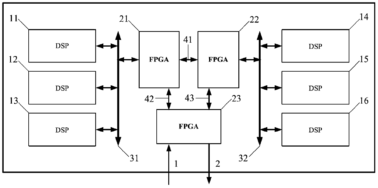

Image

  • Three-dimensional flight path planning method and device for unmanned aerial vehicle
  • Three-dimensional flight path planning method and device for unmanned aerial vehicle
  • Three-dimensional flight path planning method and device for unmanned aerial vehicle

Examples


Embodiment Construction

[0123] In order to better illustrate the purpose and advantages of the present invention. The technical solutions provided by the present invention will be described in detail below in conjunction with the accompanying drawings and specific embodiments. It should be understood that the following specific embodiments are only used to illustrate the present invention and are not intended to limit the scope of the present invention.

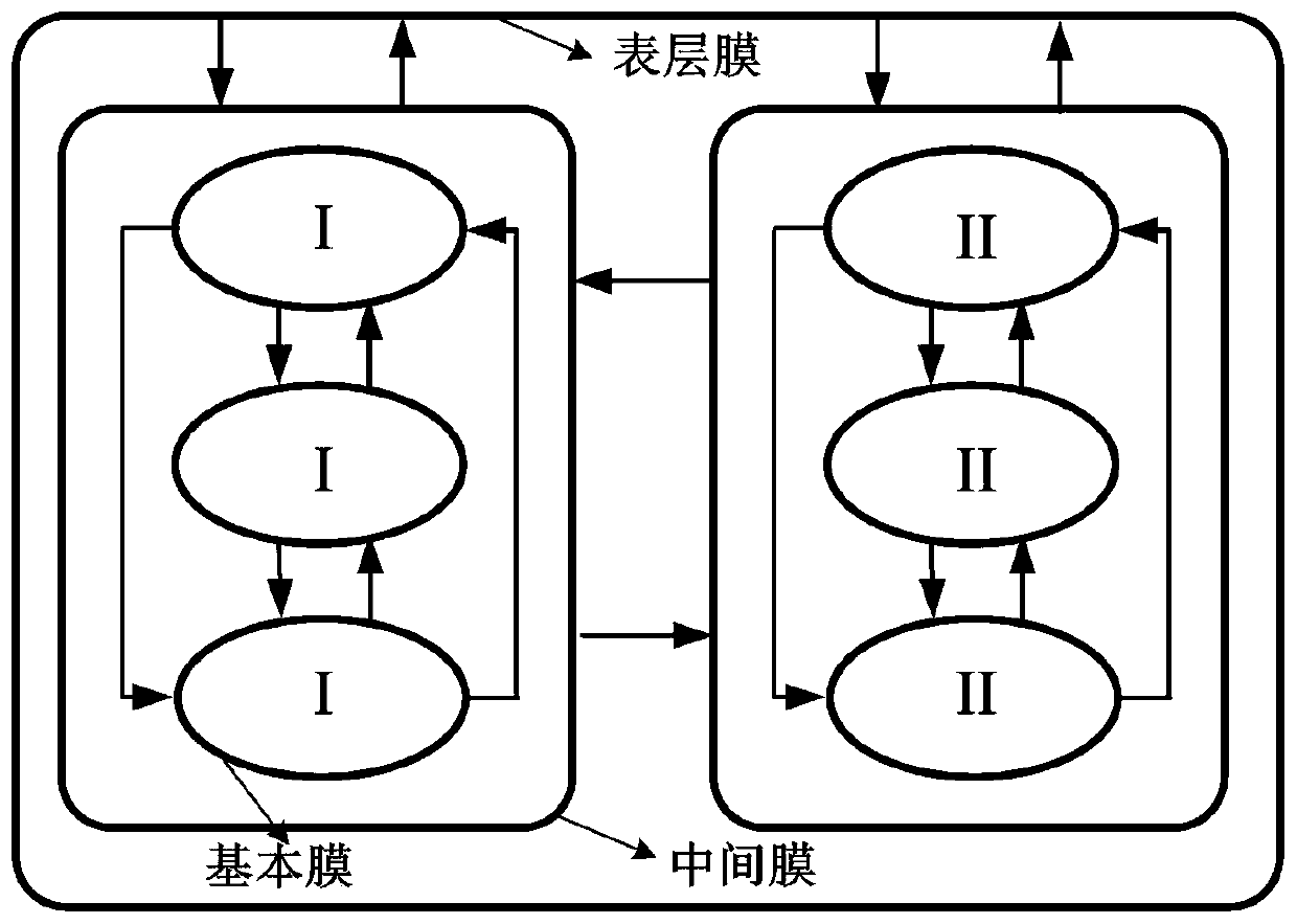
[0124] figure 1 It is a schematic diagram of the cell membrane structure in the present invention, wherein the ellipse is the basic membrane, and the basic membrane represents the trajectory planning algorithm unit in the trajectory planning method of the present invention, and each basic membrane represents a complete and independent trajectory search algorithm program; wherein There are three basic membranes for type I, and multiple basic membranes can also be set. The more basic membranes, the better the search and optimization effect, but the ha...


PUM


Abstract

The invention provides a three-dimensional flight path planning method for an unmanned aerial vehicle. The method comprises the following steps: constructing a three-dimensional terrain environment model, a flight path evaluation model and a flight path optimization constraint model; constructing a cell membrane structure; performing track search space discrete reduction and parameter initialization setting; searching an optimal track point; and performing track smoothing processing. According to the method, the global search capability of FA and the local search capability of ABC are combined, the overall search performance is enhanced, and the search probability and real-time performance of a three-dimensional flight path constructed by the method are remarkably improved; meanwhile, theinvention further provides a three-dimensional flight path planning device for the unmanned aerial vehicle, and the device comprises a cell membrane unit, a power supply unit, a clock unit, an EEPROMand an SRAM.

Description

technical field [0001] The invention belongs to the technical field of aircraft track planning, and in particular relates to a three-dimensional track planning method and a track planning device for an unmanned aerial vehicle. Background technique [0002] The rapid development of unmanned aerial vehicle (UAV, Unmanned Aerial Vehicle) technology and its application advantages have made UAV systems widely used in military / civilian fields. Among the many key technologies of the UAV system, the role of trajectory planning is to search for a feasible trajectory between the starting point and the target point that not only satisfies the physical properties of the UAV itself, but also avoids external environmental threats. Especially in the military field, efficient optimized trajectory can affect the survival and mission performance of UAVs. [0003] Wang Qiong pointed out in the document ""A Review of Commonly Used Algorithms for UAV Track Planning", Journal of Jilin University...

Claims


Application Information

Patent Timeline
Patent Type & Authority Applications(China)
IPC IPC(8): G01C21/20G06N3/00G06Q10/04
CPCG01C21/20G06N3/006G06Q10/047G05D1/0005Y02T10/40
Inventor 来磊吴德伟杨宾峰李海林邹鯤代传金
Owner AIR FORCE UNIV PLA
Learn More