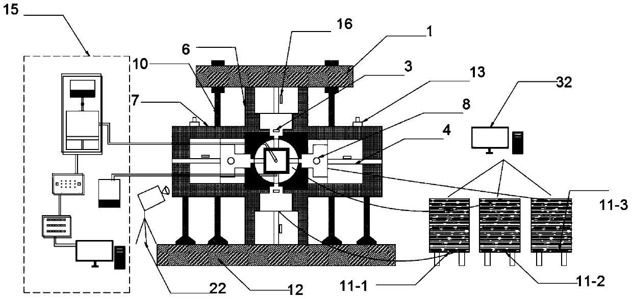
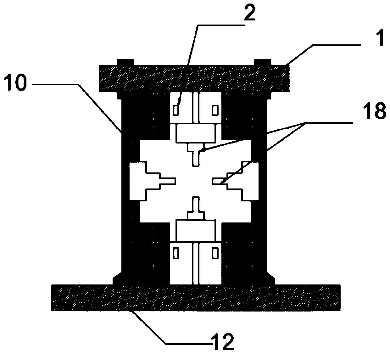
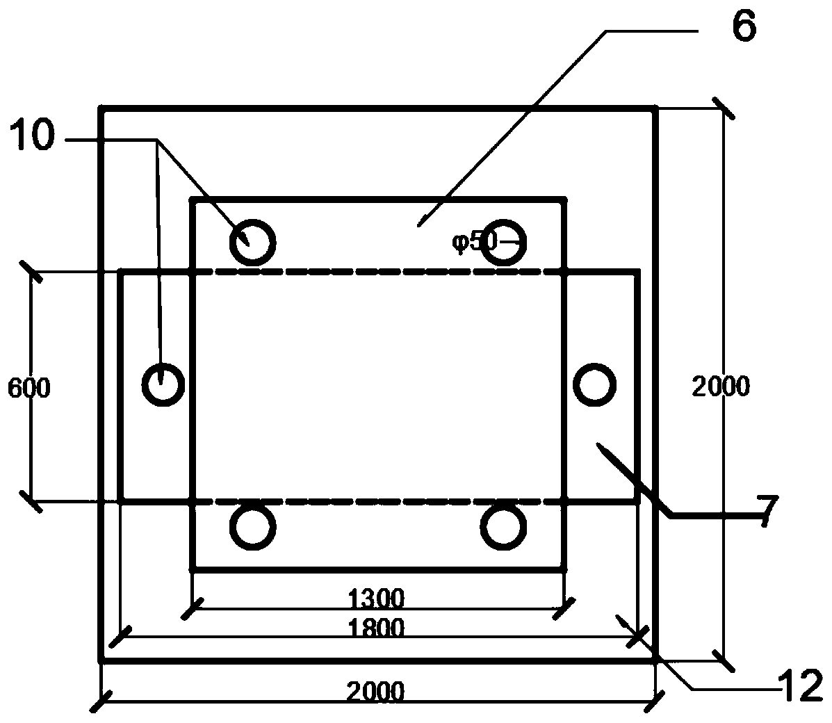
Visual true triaxial hydraulic fracturing test device and method

A technology of hydraulic splitting and testing equipment, which is applied in the direction of measuring equipment, applying stable tension/pressure to test material strength, instruments, etc., can solve the stress blank angle and end surface friction effect, poor popularization, and small hydraulic loading capacity. Application of hard rock test and other problems to achieve the effect of eliminating stress blank angle, reducing frictional resistance and uniform force

Inactive Publication Date: 2020-04-10
SHANDONG UNIV +1
View PDF8 Cites 25 Cited by
  • Summary
  • Abstract
  • Description
  • Claims
  • Application Information

AI Technical Summary

Problems solved by technology

[0004] The inventors found that there are mainly two types of true triaxial loading devices: one is the rigid loading type, and the three principal stresses are all loaded in a rigid way, but it is easy to produce the friction effect of the stress blank angle and the end face, and the visualization of the crack growth process cannot be realized; The second is the flexible loading type. At least two principal stresses are loaded by flexible hydraulic methods, but they cannot be applied to hard rock tests due to the small hydraulic loading capacity.
In addition, the true triaxial test device only conducts tests on cubic samples, and cannot perform false triaxial tests on cylinders, so the popular type is poor; at the same time, due to the tightness of the main pressure chamber of the true triaxial, it is impossible to observe the test in real time The expansion of cracks in the process

Method used


Image

  • Visual true triaxial hydraulic fracturing test device and method
  • Visual true triaxial hydraulic fracturing test device and method
  • Visual true triaxial hydraulic fracturing test device and method

Examples


Embodiment Construction

[0049] It should be pointed out that the following detailed description is exemplary and intended to provide further explanation to the present application. Unless defined otherwise, all technical and scientific terms used herein have the same meaning as commonly understood by one of ordinary skill in the art to which this application belongs.

[0050] It should be noted that the terminology used here is only for describing specific implementations, and is not intended to limit the exemplary implementations according to the present application. As used herein, unless the invention clearly states otherwise, the singular form is also intended to include the plural form. In addition, it should also be understood that when the terms "comprising" and / or "comprising" are used in this specification, their Indicate the presence of features, steps, operations, means, components and / or combinations thereof;

[0051] For the convenience of description, if the words "up", "down", "left" ...


PUM


Abstract

The invention discloses a visual true triaxial hydraulic fracturing test device and a visual true triaxial hydraulic fracturing test method. The visual true triaxial hydraulic fracturing test device comprises a vertical axial pressure loading system, a horizontal stress loading system, a confining pressure loading system and the like, wherein a hydraulic loading system adopts high-transparency oilto perform flexible servo loading on six surfaces of a rock sample, and a hydraulic loading system is mounted on a flexible loading surface to realize hydraulic fracture; in order to ensure the sealing performance of a cylinder body of a pressure chamber, oil leakage prevention elastic rubber sleeves are fixed at the contact parts of the vertical axial pressure loading system, the horizontal stress loading system and the pressure chamber; a water pressure loading system realizes hydraulic fracture through carrying out water injection on the flexible loading surface, and fracturing fluid is collected by means of a rigid water guide base plate; and a high-speed camera is used for collecting the crack propagation process of the sample in the visual pressure chamber. In addition, the visual true triaxial hydraulic fracturing test device can further complete a hydraulic fracturing test of a cylindrical sample under the condition of false triaxial loading, and meet the test requirements ofrock samples with different shapes.

Description

technical field [0001] The invention relates to a true triaxial test device, and more particularly relates to a visual true triaxial hydraulic splitting device and method capable of realizing samples of different shapes under mixed loading. Background technique [0002] Hydraulic splitting of rock mass refers to the phenomenon of cracking, damage expansion and even overall failure and instability when the rock mass produces a stress state exceeding its own limit under the action of fluid pressure, which is a typical water-rock coupling problem. In projects such as tunnel water inrush and hydropower dam water seepage, there are problems of hydraulic splitting of rock mass, causing serious disasters to construction and operation. At the same time, the application of hydraulic splitting technology has accelerated the rapid development of modern petroleum industry, shale gas exploitation, geothermal resource development, nuclear waste storage, coal seam mining and other fields, ...

Claims


Application Information

Patent Timeline
Patent Type & Authority Applications(China)
IPC IPC(8): G01N3/12G01N3/02
CPCG01N3/02G01N3/12G01N2203/0019G01N2203/0048G01N2203/0256
Inventor 杨为民高雪池耿阳齐辉王利戈王爱涛孙子正胡超丁若松孔军
Owner SHANDONG UNIV
Why Eureka
Try Eureka