Energy storage device management circuit for new energy power generation and control method thereof

A charging control method and energy storage device technology, applied in the electronic field, can solve the problems of fast voltage drop and large load impact, and achieve the effect of improving output capacity and efficiency and suppressing the drop of output voltage

Active Publication Date: 2020-04-10
GREE ELECTRIC APPLIANCES INC
View PDF6 Cites 0 Cited by
  • Summary
  • Abstract
  • Description
  • Claims
  • Application Information

AI Technical Summary

Problems solved by technology

Compared with lithium batteries, supercapacitors have a long life and high power density, making them suitable for energy storage. However, with the release of electric energy, the lower the voltage across supercapacitors, the faster their voltage drops, which has a great impact on the load.

Method used


Image

  • Energy storage device management circuit for new energy power generation and control method thereof
  • Energy storage device management circuit for new energy power generation and control method thereof
  • Energy storage device management circuit for new energy power generation and control method thereof

Examples


Embodiment 1

[0046] Embodiment 1, a control method of an energy storage device management circuit for new energy power generation.

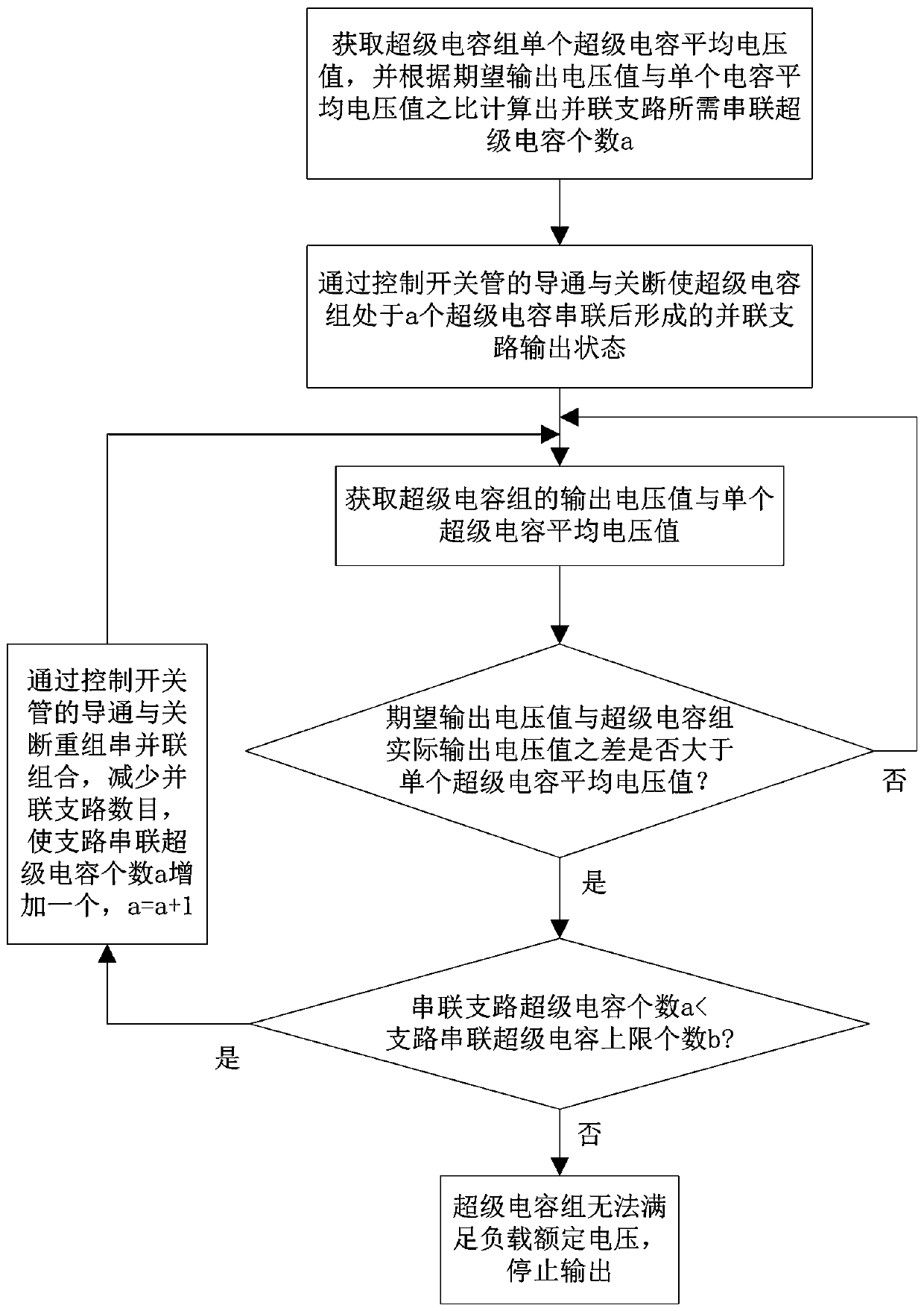
[0047] When the supercapacitor supplies power to the load, its output voltage will drop with the release of electric energy, especially when the energy storage is low. According to the formula E=1 / 2C*U2, the output voltage will drop faster and faster. As a result, there will be a large part of the remaining supercapacitor that cannot provide output power to the load, thereby reducing the output capability and efficiency of the supercapacitor bank.

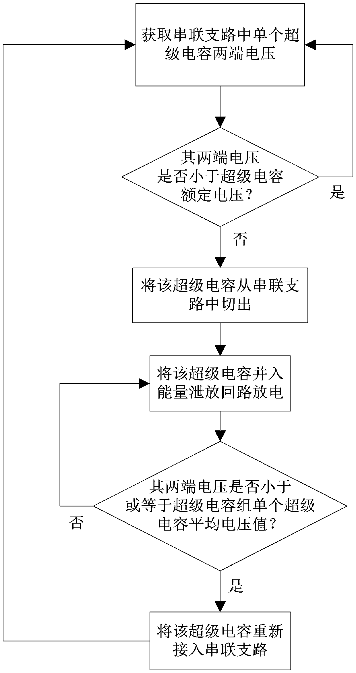
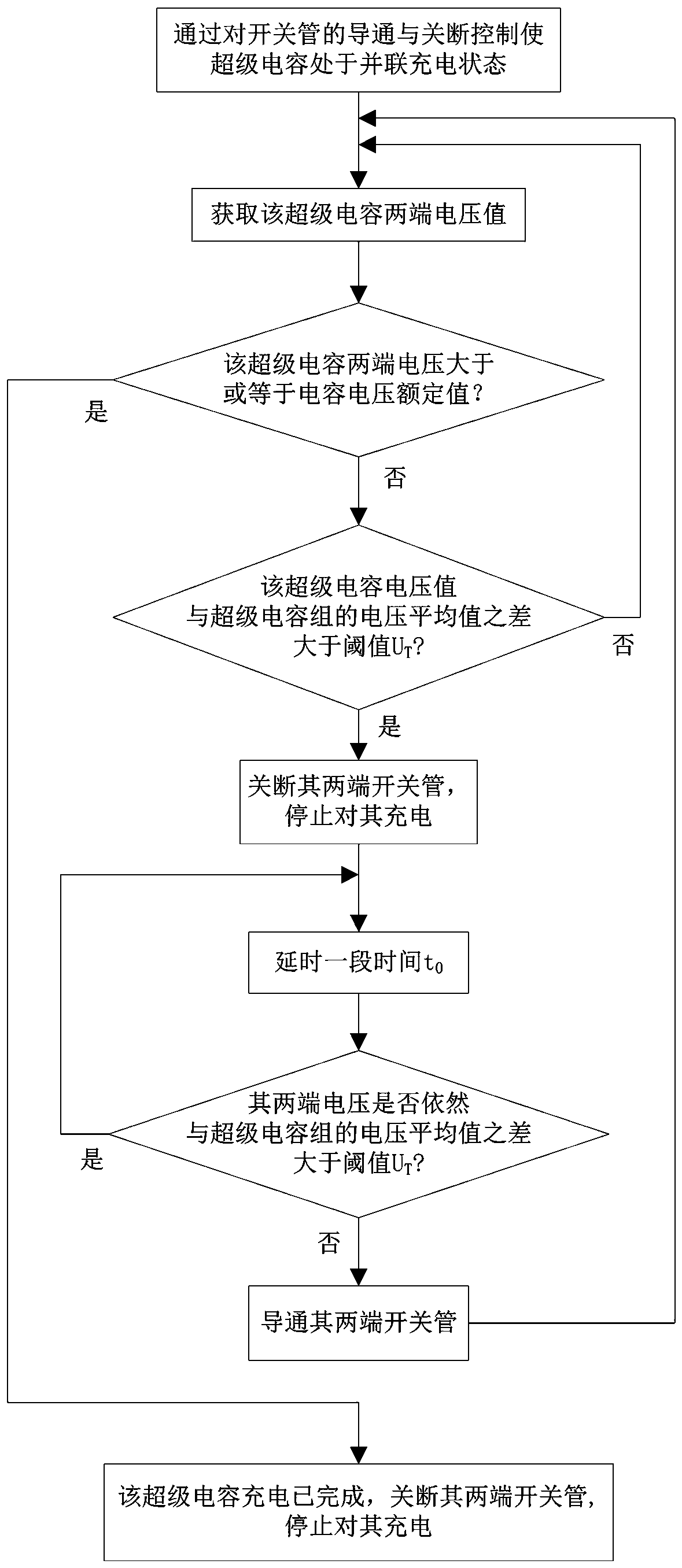
[0048] For this reason, this embodiment provides a control method for the management circuit of the energy storage device for new energy power generation, which is applied to the attached Figure 4 The energy storage device management circuit for new energy power generation shown includes a charging control method and a discharging control method, as shown in the attached figure 1 As shown, the discharge control ...

Embodiment 2

[0083] Embodiment 2, an energy storage device management circuit for new energy power generation.

[0084] as attached Figure 4 As shown, this embodiment provides an energy storage device management circuit for new energy power generation, and the energy storage device management circuit for new energy power generation is applied to the control of the energy storage device management circuit for new energy power generation described in Embodiment 1 method.

[0085] The energy storage device management circuit for new energy power generation includes a supercapacitor group, and the supercapacitor group has n supercapacitors, the positive pole of each supercapacitor is connected to the positive pole DC+ of the power supply through a switch tube, and each supercapacitor The negative poles of the capacitors are all connected to the negative pole DC- of the power supply through the switch tube, and the negative pole of the nth supercapacitor is also connected to the positive pole...


PUM


Abstract

The invention provides an energy storage device management circuit for new energy power generation and a control method thereof, the control method comprises a charging control method and a discharging control method, and the discharging control method selects a super capacitors in a super capacitor group according to an expected output voltage value to form a series branch output voltage; when the difference between the expected output voltage value and the actual output voltage value of the super capacitor bank is larger than the average voltage value of the super capacitors and the number of the super capacitors of the series branch is smaller than the upper limit number b, one super capacitor output voltage is added to the series branch; and when the number of the super capacitors of the series branch reaches the upper limit number b, the super capacitor bank stops outputting the voltage. The output voltage value of the super capacitor bank can be adjusted, the output voltage of the super capacitor bank is effectively prevented from decreasing on the premise that the load capacity of the super capacitor bank is guaranteed, the load can consume electric energy stored in the super capacitor bank as much as possible, and then the output capacity and efficiency of the super capacitor bank are improved.

Description

technical field [0001] The invention relates to the field of electronic technology, in particular to a management circuit and control method of an energy storage device for new energy power generation. Background technique [0002] In recent years, with global warming, large-scale reduction of glaciers, and rising sea levels, people's awareness of environmental protection has gradually increased. Energy conservation and emission reduction have become a hot topic in the energy field. Environmentally friendly development has become a mainstream trend. Various new energy Technology developed rapidly during this period. [0003] Traditional energy relies on the combustion of fossil fuels. On the one hand, fossil fuels are non-renewable. On the other hand, the combustion of fossil fuels will emit sulfur compounds, carbon dioxide, and PM2.5, which cause greenhouse effects or are harmful to humans. New energy is the use of some renewable resources in nature, such as solar energy, ...

Claims


Application Information

Patent Timeline
Patent Type & Authority Applications(China)
IPC IPC(8): H02J7/34
CPCH02J7/345
Inventor 李林洪关福成徐耀龙庞伟刘杰
Owner GREE ELECTRIC APPLIANCES INC
Why Eureka
Try Eureka