Oil removing and degreasing device and method for heat treatment production line

A degreasing device and production line technology, which is applied in the field of heat treatment, can solve the problems of complex curvature of the workpiece with grooves and threads, difficulty in removing surface grease, and reduced metal strength, etc., to achieve thorough removal, reduce waste, and improve use efficiency.

Inactive Publication Date: 2020-04-14
嘉兴兴欣环保科技股份有限公司
View PDF7 Cites 6 Cited by
  • Summary
  • Abstract
  • Description
  • Claims
  • Application Information

AI Technical Summary

Problems solved by technology

[0002] The degreasing before heat treatment should be to remove the organic matter on the surface, so as to avoid the decomposition of these organic matter at high temperature and produce harmful gases. It is especially important that if the organic matter decomposes to generate hydrogen, the hydrogen will enter the metal at high temperature, causing hydrogen embrittlement, making the metal greatly reduced strength
[0003] At present, when heat-treated metal parts are degreased, the workpiece is soaked in the degreasing pool for a period of time, and then the workpiece is fished out. This method is suitable for workpieces with smooth surfaces, but it is suitable for workpieces with complex curved surfaces, grooves and threads. situation, it is difficult to remove surface grease, so a degreasing and degreasing device that can remove complex surfaces is needed

Method used


Image

  • Oil removing and degreasing device and method for heat treatment production line
  • Oil removing and degreasing device and method for heat treatment production line
  • Oil removing and degreasing device and method for heat treatment production line

Examples


Embodiment Construction

[0028] The technical solutions in the embodiments of the present invention will be clearly and completely described below with reference to the accompanying drawings in the embodiments of the present invention. Obviously, the described embodiments are only a part of the embodiments of the present invention, but not all of the embodiments. Based on the embodiments of the present invention, all other embodiments obtained by those of ordinary skill in the art without creative efforts shall fall within the protection scope of the present invention.

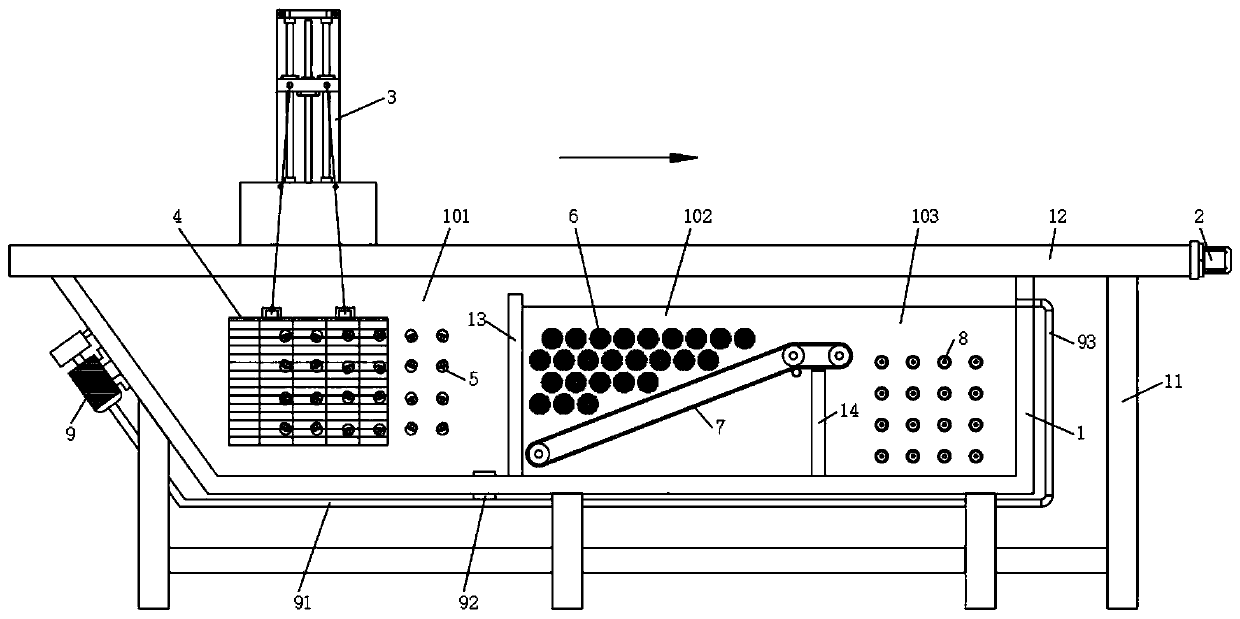
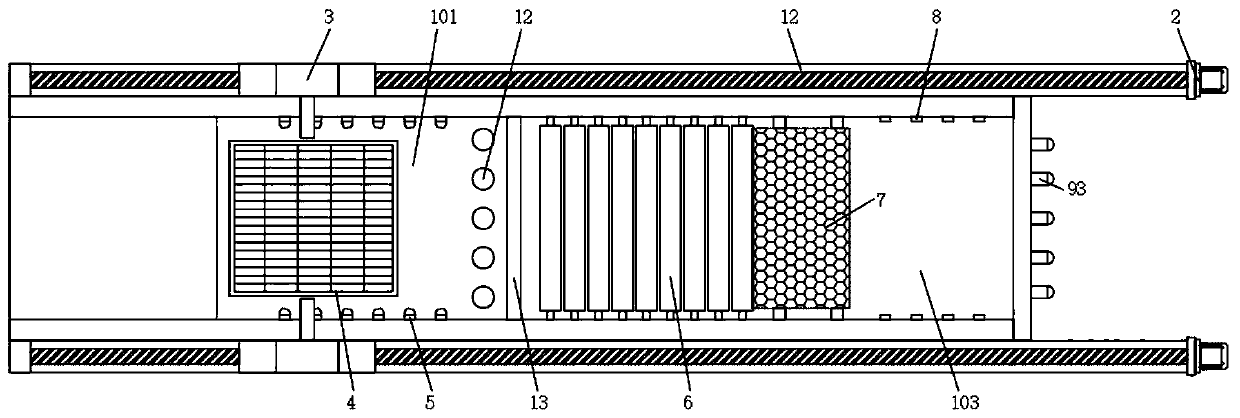
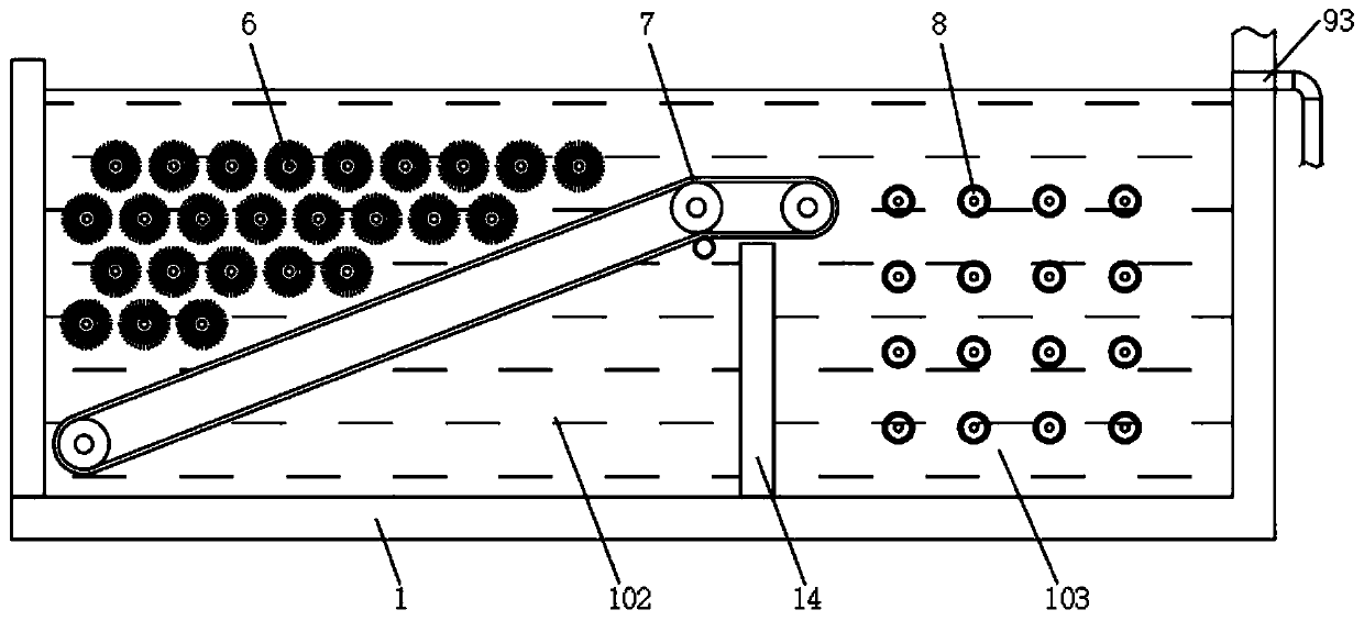
[0029] see Figure 1-4 , the present invention provides the following technical solutions: the degreasing and degreasing device and method for the heat treatment production line, including a degreasing tank 1 and several support legs 11 fixed on the bottom of the degreasing tank 1, and the inside of the degreasing tank 1 is fixed with a first partition 13 and the second partition 14, the inside of the degreasing pool 1 is separated by...


PUM


Abstract

The invention belongs to the technical field of heat treatment and particularly relates to an oil removing and degreasing device and method for a heat treatment production line. The device comprises adegreasing tank and a plurality of supporting legs fixed to the bottom of the degreasing tank, wherein a first partition plate and a second partition plate are fixedly arranged in the degreasing tank, and the interior of the degreasing tank is divided into a flushing tank, a scrubbing tank and an ultrasonic cleaning tank by the first partition plate and the second partition plate. The flushing tank, the scrubbing tank and the ultrasonic cleaning tank are arranged in the degreasing tank, a workpiece is washed in the washing tank, relatively obvious grease attached to a surface is removed, through a plurality of layers of roller brushes, the workpiece surface is carefully cleaned and brushed, the workpiece surface can make full contact with a complex surface, then the workpiece is conveyedinto the ultrasonic cleaning tank after being brushed and is cleaned through ultrasonic waves in cooperation with grease removing liquid, the grease on the workpiece surface can be removed more thoroughly, the cleaning liquid is used in a classified mode, the cleaning degree of the cleaning liquid is guaranteed, and waste of the cleaning liquid is reduced.

Description

technical field [0001] The invention belongs to the technical field of heat treatment, and in particular relates to an oil removal and degreasing device and method for a heat treatment production line. Background technique [0002] The degreasing before heat treatment should be to remove the organic matter on the surface, so as to avoid the decomposition of these organic matter at high temperature and produce harmful gases. It is especially important that if the organic matter decomposes to generate hydrogen, the hydrogen will enter the metal at high temperature, causing hydrogen embrittlement, making the metal The strength is greatly reduced. [0003] At present, when heat-treated metal parts are degreased, the workpiece is soaked in the degreasing pool for a period of time, and then the workpiece is fished out. This method is suitable for workpieces with smooth surfaces, but for complex curved workpieces with grooves and threads. In some cases, it is difficult to remove s...

Claims


Application Information

Patent Timeline
Patent Type & Authority Applications(China)
IPC IPC(8): B08B3/02B08B3/08B08B3/12B08B3/14B08B1/04B08B13/00C23G3/00
CPCB08B1/002B08B1/04B08B3/022B08B3/08B08B3/12B08B3/14B08B13/00C23G3/00
Inventor 姚惠锋陈卫良黄春松
Owner 嘉兴兴欣环保科技股份有限公司
Why Eureka
Try Eureka