Scrap removing device for wood processing

A wood and workbench technology, applied in the field of wood processing, can solve the problems of low practicability, occupying a large space, complicated and time-consuming operation, etc., and achieves increased convenience, increased collection area, and convenient installation and disassembly. another effect

Inactive Publication Date: 2020-04-14
河北聚商智能科技有限公司
View PDF7 Cites 4 Cited by
  • Summary
  • Abstract
  • Description
  • Claims
  • Application Information

AI Technical Summary

Problems solved by technology

[0003] Common wood collection devices currently on the market generally face the problem that when users collect wood chips, they directly store the wood chips in the storage box, and then take out the raw materials, and the wood chips are relatively fluffy when stored, and less wood chips will occupy The large space makes the storage box load less wood chips each time, so the user must clean the storage box frequently. The operation is cumbersome, time-consuming and laborious, and its practicality is not strong.

Method used


Image

  • Scrap removing device for wood processing
  • Scrap removing device for wood processing
  • Scrap removing device for wood processing

Examples


Embodiment 1

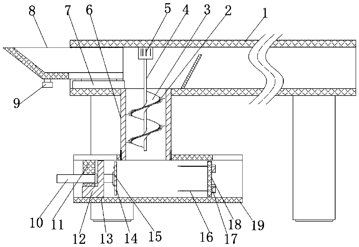
[0030] refer to Figure 1-5 , a waste removal device for wood processing, including a workbench 1 with a cavity in a square tubular structure, a round hole is opened at the bottom of the workbench 1 near the edge, and a feeding pipe 6 is welded in the round hole, The top inner wall of the workbench 1 is fixed with a driving motor 5 close to the top of the feeding pipe 6, and the top of the output shaft of the driving motor 5 is fixed with a transmission rod 4 through a coupling, and the outer wall of the transmission rod 4 is provided with a spiral plate 3. And the circumferential edge of the spiral plate 3 is provided with tentacles 2 that are distributed equidistantly, and the upper and lower sides of the spiral plate 3 are provided with staggered barbs, which increases the friction with the sawdust, so that the lower and lower sides can be rotated when rotating. The wood waste near the mouth of the material pipe 6 is quickly twisted into the discharge pipe 6, and when it ne...

Embodiment 2

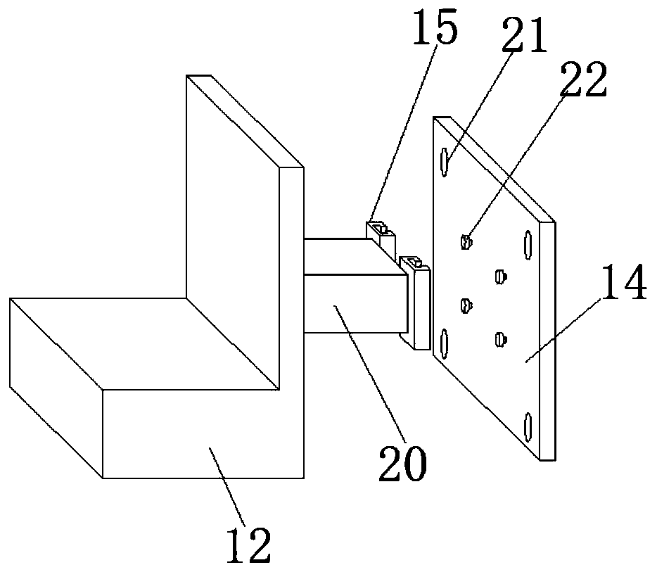
[0039] refer to Figure 1-4 , a waste removal device for wood processing. Compared with Embodiment 1, this embodiment also includes two channel steel columns 15 parallel to each other fixed on the side of the fixed block 20 near the moving push plate 14, and the moving push plate The side of 14 is nailed with the nail that matches with channel steel column 15 inner groove size.

[0040] Wherein, the distance between two adjacent rows of nails is equal to the distance between two channel steel columns 15, so that a new mobile push plate 14 can be pushed out from the left side opening 1902 of the feeding pipe 6 before compression. Slowly insert it into the channel steel column 15 and get final product, the installation and disassembly are very convenient and firm.

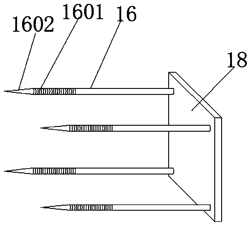
[0041] Wherein, the end of extension push rod 16 is provided with tip 1602, and the end of extension push rod 16 near tip 1602 is provided with screw thread 1601, and then from the left side of mobile push plate 14 ...


PUM


Abstract

The invention belongs to the technical field of wood processing, in particular to a scrap removing device for wood processing, and aims at solving the problem that in wood processing at present, scraps are simply sucked into a collecting barrel for collecting and fluffy scrap occupy a large amount of space. The scarp removing device comprises a workbench of a square-tube-shaped structure and internally provided with a cavity, a round hole is formed in the position, close to the edge, of the bottom of the workbench, a discharging pipe is welded in the round hole, a driving motor is fixed over the position, close to the discharging pipe, of the inner wall of the top end of the workbench, a transmission rod is fixed to the top end of an output shaft of the driving motor through a coupler, anda spiral plate is arranged on the circumferential outer wall of the transmission rod. According to the scrap removing device, wood waste chips near the pipe opening of the discharging pipe can be rapidly twisted into the discharging pipe during rotation, scrap can be stopped in the discharging pipe when discharging is not needed, and cleaning work at an outlet is facilitated.

Description

technical field [0001] The invention relates to the technical field of wood processing, in particular to a waste removal device for wood processing. Background technique [0002] Wood processing requires cutting and other operations to obtain high-quality wood, and a large amount of wood chips will be produced during processing. Wood chips are used for many purposes, such as fuel or paper-making raw materials, so people will use wood chip collection devices to collect wood chips. . [0003] Common wood collection devices currently on the market generally face the problem that when users collect wood chips, they directly store the wood chips in the storage box, and then take out the raw materials, and the wood chips are relatively fluffy when stored, and less wood chips will occupy The larger space makes the wood chips loaded in the storage box less each time, and the user must clean the storage box frequently. The operation is complicated, time-consuming and laborious, and ...

Claims


Application Information

Patent Timeline
Patent Type & Authority Applications(China)
IPC IPC(8): B27G3/00B27M1/02B27N5/00
CPCB27G3/00B27M1/02B27N5/00
Inventor 张振远
Owner 河北聚商智能科技有限公司
Why Eureka
Try Eureka