A waste removal device for wood processing
A wood and workbench technology, applied in the field of wood processing, can solve the problems of occupying a large space, cumbersome and complicated operation, time-consuming and labor-intensive, and poor practicability.
- Summary
- Abstract
- Description
- Claims
- Application Information
AI Technical Summary
Problems solved by technology
Method used
Image
Examples
Embodiment 1
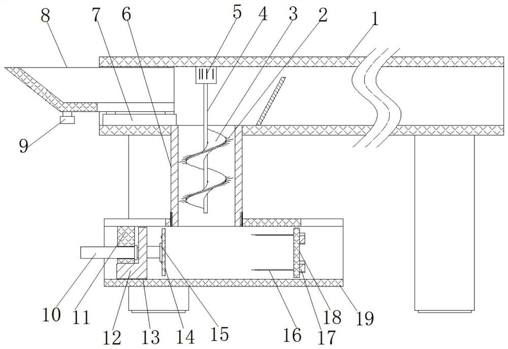
[0030] refer to Figure 1-5 , a waste removal device for wood processing, including a workbench 1 with a cavity in a square tubular structure, a round hole is opened at the bottom of the workbench 1 near the edge, and a feeding pipe 6 is welded in the round hole, The top inner wall of the workbench 1 is fixed with a driving motor 5 close to the top of the feeding pipe 6, and the top of the output shaft of the driving motor 5 is fixed with a transmission rod 4 through a coupling, and the outer wall of the transmission rod 4 is provided with a spiral plate 3. And the circumferential edge of the spiral plate 3 is provided with equidistantly distributed antennae 2, and the upper and lower sides of the spiral plate 3 are provided with barbs that are staggered, which increases the friction with the sawdust, so that it can be rotated. The wood waste near the mouth of the feeding pipe 6 is quickly twisted into the feeding pipe 6, and when it needs to be discharged, it can be rotated t...
Embodiment 2
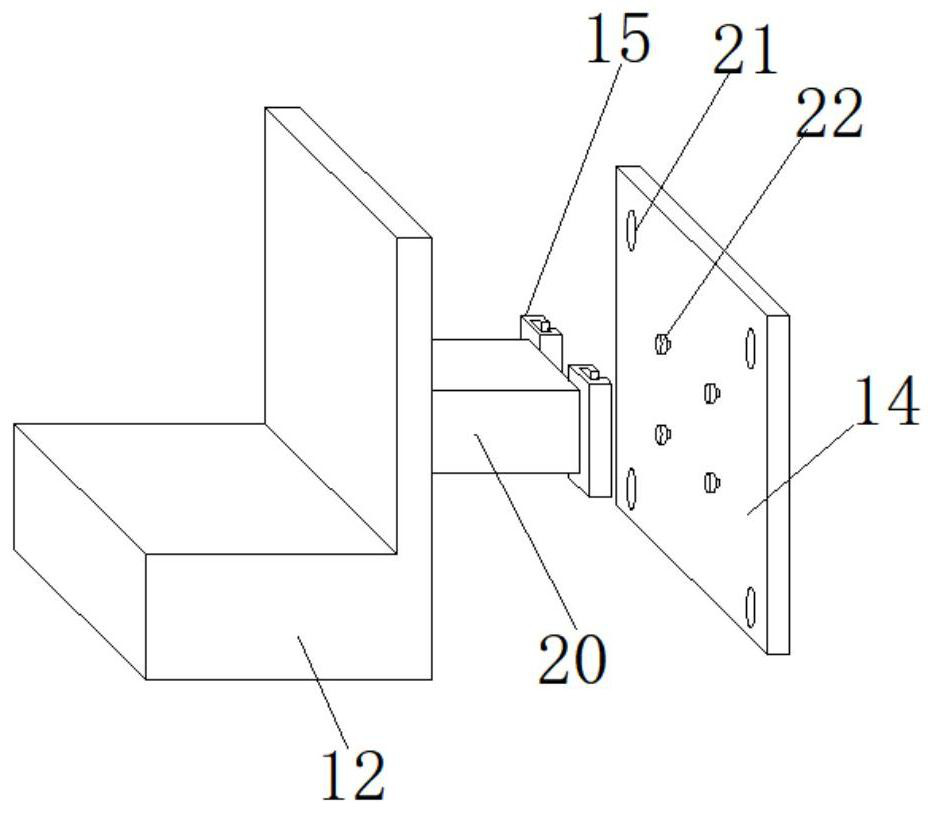
[0039] refer to Figure 1-4 , a waste removal device for wood processing. Compared with Embodiment 1, this embodiment also includes two channel steel columns 15 parallel to each other fixed on the side of the fixed block 20 near the moving push plate 14, and the moving push plate The side of 14 is nailed with the nail that matches with channel steel column 15 inner groove size.
[0040] Wherein, the distance between two adjacent rows of nails is equal to the distance between two channel steel columns 15, so that a new mobile push plate 14 can be pushed out from the left side opening 1902 of the feeding pipe 6 before compression. Slowly insert it into the channel steel column 15 and get final product, the installation and disassembly are very convenient and firm.
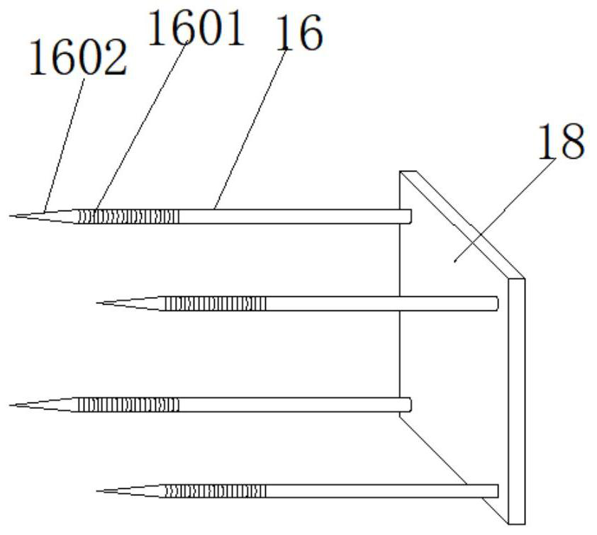
[0041] Wherein, the end of extension push rod 16 is provided with tip 1602, and the end of extension push rod 16 near tip 1602 is provided with screw thread 1601, and then from the left side of mobile push plate 14 ...
PUM
 Abstract
Description
Claims
Application Information
 - R&D
- Intellectual Property
- Life Sciences
- Materials
- Tech Scout
- Unparalleled Data Quality
- Higher Quality Content
- 60% Fewer Hallucinations
Browse by: Latest US Patents, China's latest patents, Technical Efficacy Thesaurus, Application Domain, Technology Topic, Popular Technical Reports.
© 2025 PatSnap. All rights reserved.Legal|Privacy policy|Modern Slavery Act Transparency Statement|Sitemap|About US| Contact US: help@patsnap.com


