
Digital phase-locked loop frequency synthesizer

A frequency synthesizer, digital phase-locked loop technology, applied in the direction of automatic power control, electrical components, etc., can solve the disadvantages of digital phase-locked loop frequency synthesizer low power consumption and low-cost integration, large chip area, large power consumption Consumption and other issues to achieve the effect of saving area and power consumption, simplifying circuit design, and speeding up the loop locking process

Pending Publication Date: 2020-04-14
HUAZHONG UNIV OF SCI & TECH
View PDF0 Cites 3 Cited by
  • Summary
  • Abstract
  • Description
  • Claims
  • Application Information

AI Technical Summary

Problems solved by technology

[0004] It can be seen that the traditional constant resolution time-to-digital converter needs to occupy a considerable chip area and consume a large power consumption, which is not conducive to the low power consumption and low-cost integration requirements of the digital phase-locked loop frequency synthesizer

Method used


Image

  • Digital phase-locked loop frequency synthesizer
  • Digital phase-locked loop frequency synthesizer
  • Digital phase-locked loop frequency synthesizer

Examples


Embodiment Construction

[0022] The present invention will be further described below in conjunction with specific embodiment:

[0023] Take the design of a digital PLL frequency synthesizer with input 32.768kHz and output 16MHz as an example.

[0024] (1) System structure design

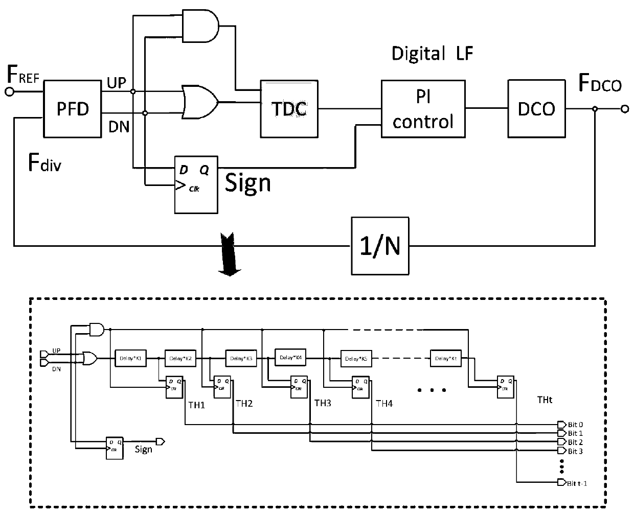
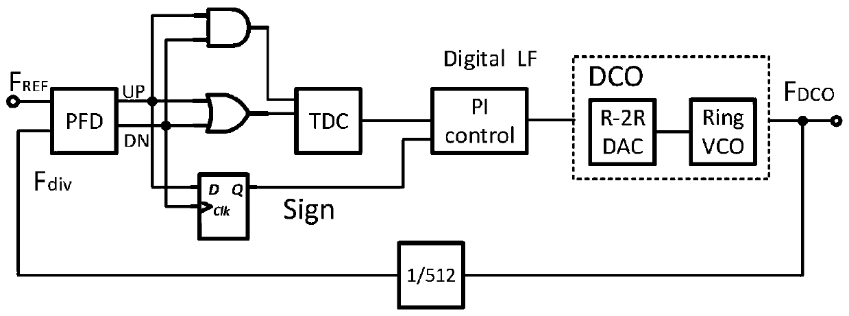
[0025] Due to the need to achieve fixed frequency synthesis from 32kHz to 16MHz, the frequency division ratio N is set to 512, and the system block diagram is as follows image 3 shown. PFD will input reference frequency signal F REF and frequency divider output frequency signal F div The phase difference of the signal is converted into UP and DN signals, and then the UP and DN signals are processed by the gate circuit, and output two square wave signals with different pulse widths to the TDC module; the phase difference signal is converted into a corresponding digital signal by the TDC module, and output The sign bit indicating the positive and negative of the phase difference; the digital filter uses a proportional-in...


PUM


Abstract

The invention discloses a digital phase-locked loop frequency synthesizer based on a Fibonacci sequence time-to-digital converter. The digital phase-locked loop frequency synthesizer comprises a phasefrequency detector module, a time-to-digital converter TDC module, a proportional integral controller module, a digital control oscillator module and a frequency divider module. The TDC module is composed of t D triggers and a time delay unit. The D triggers directly output binary digital signals. Specifically, the output of the D flip-flop is multiplied by a corresponding Fibonacci coefficient fn, the delay units are multiplied by a corresponding delay time coefficient n = 1... T, and the value of t depends on the requirements of input reference frequency and output frequency. Compared witha TDC with a traditional structure, the TDC has the advantages that the number of required D triggers and delay units is greatly reduced, a decoder circuit is not required, and the chip area and powerconsumption are greatly reduced; the phase-locked loop can be locked, and the locking time is equivalent to that of a digital phase-locked loop based on a traditional structure TDC.

Description

technical field [0001] The invention relates to the technical field of digital phase-locked loops, in particular to a digital phase-locked loop frequency synthesizer based on a Fibonacci sequence time-to-digital converter. Background technique [0002] In a digital phase-locked loop frequency synthesizer, a time-to-digital converter (TDC, Time Digital Converter) is a very important module, which converts the phase difference information between an input reference clock signal and an output feedback clock signal into a digital signal. Generally, the detection range of phase difference is about 0-0.25π, which can meet the requirement of loop locking. If the phase difference signal detection range of TDC is 0-0.25π, then the detection of the phase difference signal within 0-0.25π is linear; if the phase difference signal exceeds 0.25π, the digital signal output by TDC and the phase difference signal are 0.25 When π, the corresponding digital signal is the same and does not cha...

Claims


Application Information

Patent Timeline
IPC IPC(8): H03L7/08H03L7/087H03L7/099H03L7/18
CPCH03L7/0802H03L7/0805H03L7/087H03L7/0992H03L7/18
Inventor 陈晓飞丁鹤唐敔翔李钰莹汪洋
Owner HUAZHONG UNIV OF SCI & TECH
Learn More