
A tubular reactor

A shell-and-tube reactor and the technology of the reactor are applied in the field of reactors, which can solve the problems of potential explosion of combustible gas raw materials, uneven gas-liquid flow field/temperature distribution, uneven heat distribution, etc., so as to avoid the self-polymerization explosion of feed materials. The effect of eliminating hidden dangers, eliminating dead zones and stagnant layers, and reducing process energy consumption

Active Publication Date: 2022-03-22
JIANGSU OXIRANCHEM CO LTD
View PDF6 Cites 0 Cited by
  • Summary
  • Abstract
  • Description
  • Claims
  • Application Information

AI Technical Summary

Problems solved by technology

[0003] What the present invention is to solve is the following problems existing in the prior art: (1) uneven gas-liquid flow field / temperature distribution leads to uneven heat distribution and causes local overheating or incomplete reaction, which affects catalyst service life and product yield; 2) The local channel flow of the gas-liquid separate chamber feed causes the gas feed in the liquid chamber to form a dead zone and a stagnant layer. At high temperatures, the combustible gas raw materials are prone to self-accumulation and there is a risk of explosion

Method used


Image

  • A tubular reactor

Examples


Embodiment 1

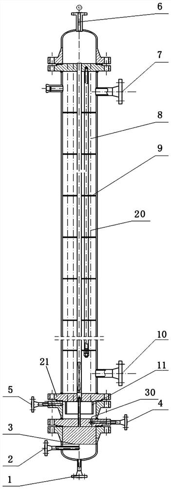
[0044] Ethylene carbonate synthesis: according to figure 1 , The gas-liquid-solid multiphase tubular reactor is installed vertically, with 2400 tubes evenly distributed inside the reactor, the inner diameter of the tubes is 20mm, the distance between the tubes is 15mm, and the length of the tubes is 8000mm. The number of baffles is 10, forming an angle of 90° with the shell. Each column is filled with an organic polymer-supported ionic liquid catalyst (a polystyrene resin-supported 1,2,4-triazole bromide-based ionic liquid catalyst is specifically used in the present invention). CO 2 It enters from the gas inlet and is evenly distributed into the tube reactor through the gas inlet distributor. Ethylene oxide (EO) is fed tangentially through the liquid feed port, and the baffle is located at the top of the liquid feed chamber and is 10mm away from the bottom of the liquid feed chamber. The tangential feeding and baffle adjustment method is used to feed the feed to eliminate ...

Embodiment 2

[0046] Sulfonation (sulfation) reaction: according to figure 1 , The tube-and-tube reactor is installed vertically, with 2,200 tubes evenly distributed inside the reactor, the inner diameter of the tubes is 25mm, the distance between the tubes is 12mm, and the length of the tubes is 6m. The number of baffles inside the tube-and-tube reactor is 5, and it forms an angle of 90° with the shell. SO 3 / Nitrogen mixture (SO 3 The volume fraction is 25%) enters from the gas inlet, and is evenly distributed into the tube-and-tube reactor through the gas inlet distributor. The organic phase is fed tangentially through the liquid feed port, and the baffle is located at the top of the liquid feed chamber and 8mm from the bottom of the liquid feed chamber. The tangential feed baffle is used to adjust the feed to eliminate the disturbance caused by the feed, and the organic liquid phase can be evenly distributed into each tube, SO 3 Uplink reacts with the organic liquid phase to produce...


PUM


Abstract

The application provides a tube-and-tube reactor, which includes: a reactor box, a plurality of tubes arranged at intervals in the reactor box, a heat exchange medium inlet and a heat exchange medium arranged on the reactor box. An exchange medium outlet, and one or more baffles located between the heat exchange medium inlet and the heat exchange medium outlet, a reactor outlet arranged on the upper part of the reactor box, a gas feed unit and a liquid inlet material unit, and gas distributor. The tube-and-tube reactor of the present invention adopts gas-liquid separate cavity feeding, and proposes a way of adjusting the feeding by tangential feeding and baffles, which realizes the uniform distribution of gas and liquid into each tube, and eliminates the dead zone in the liquid cavity And stagnant layer, avoiding the hidden danger of feed material self-polymerization explosion.

Description

technical field [0001] The present application relates to the field of reactors, in particular to a tube-and-tube reactor, and more specifically to a tube-and-tube fixed-bed catalytic reactor. Background technique [0002] The shell and tube reactor is composed of many very thin reaction tubes, and these reaction tubes are filled with catalysts to become a fixed bed reactor. The shell and tube reactor is mostly used in the case of strong exothermic reaction, strong endothermic reaction and other reactions that proceed very quickly, and can be used for the preparation of ethylene carbonate. The current feeding method for preparing ethylene carbonate with this type of equipment is mainly that both gas and liquid are fed from the bottom cavity in the same cavity, which easily leads to uneven distribution of liquid. How to solve the uneven gas-liquid distribution, local flow stagnation, slow heat transfer and low reaction efficiency of carbonylation reaction are the engineering...

Claims


Application Information

Patent Timeline
Patent Type & Authority Patents(China)
IPC IPC(8): B01J8/06
CPCB01J8/067
Inventor 朱建民刘兆滨董振鹏顾晓华田威俞欢
Owner JIANGSU OXIRANCHEM CO LTD
Learn More