
Carbon steel impeller assembling and welding device, and method

A welding device and impeller technology, applied in auxiliary devices, welding equipment, auxiliary welding equipment, etc., can solve the problems of low efficiency of manual welding of blades, waste of manpower, material resources and costs, affecting the quality of impellers, etc., to achieve excellent machining performance, reduce Processing difficulty and cost, stable and reliable effect of disassembly and assembly

Pending Publication Date: 2020-04-17
YANTAI WALU ROBOT AUTOMATION CO LTD
View PDF0 Cites 3 Cited by
  • Summary
  • Abstract
  • Description
  • Claims
  • Application Information

AI Technical Summary

Problems solved by technology

At present, the existing welding method of the impeller usually adopts manual welding, draw auxiliary lines on the center disk of the impeller, then weld the blades on the center disk one by one, and finally weld the upper and lower cone disks on the top of the blades, and weld the blades together. The first step is very important. The accuracy of blade welding will directly affect the quality of the entire impeller, while the efficiency of manual blade welding is extremely low, and the welding accuracy is not high, the product qualification rate is low, and waste of manpower, material resources and costs

Method used


Image

  • Carbon steel impeller assembling and welding device, and method
  • Carbon steel impeller assembling and welding device, and method
  • Carbon steel impeller assembling and welding device, and method

Examples


Embodiment 1

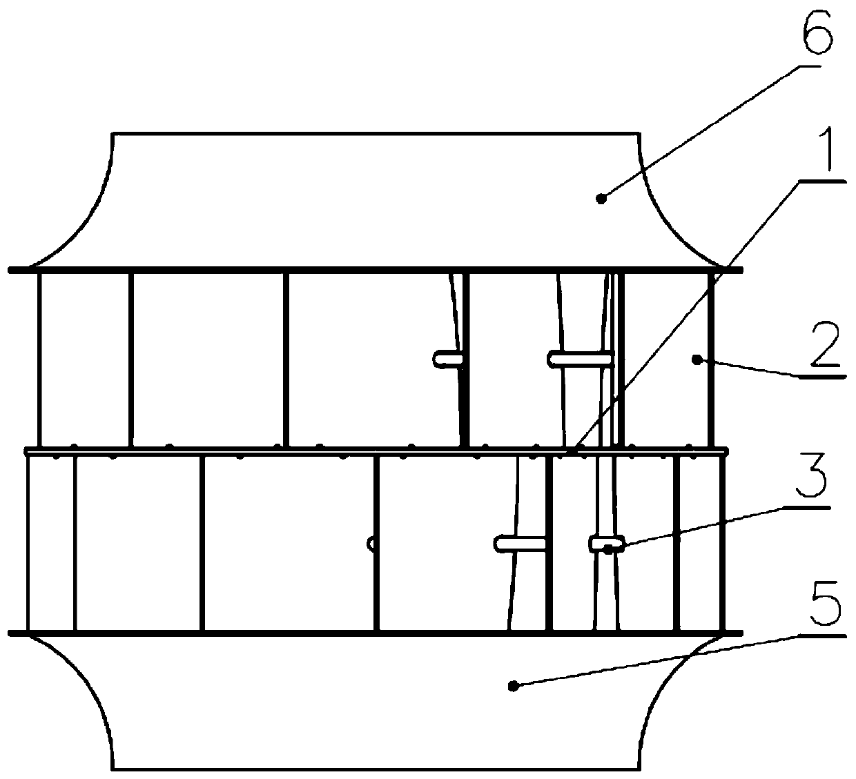
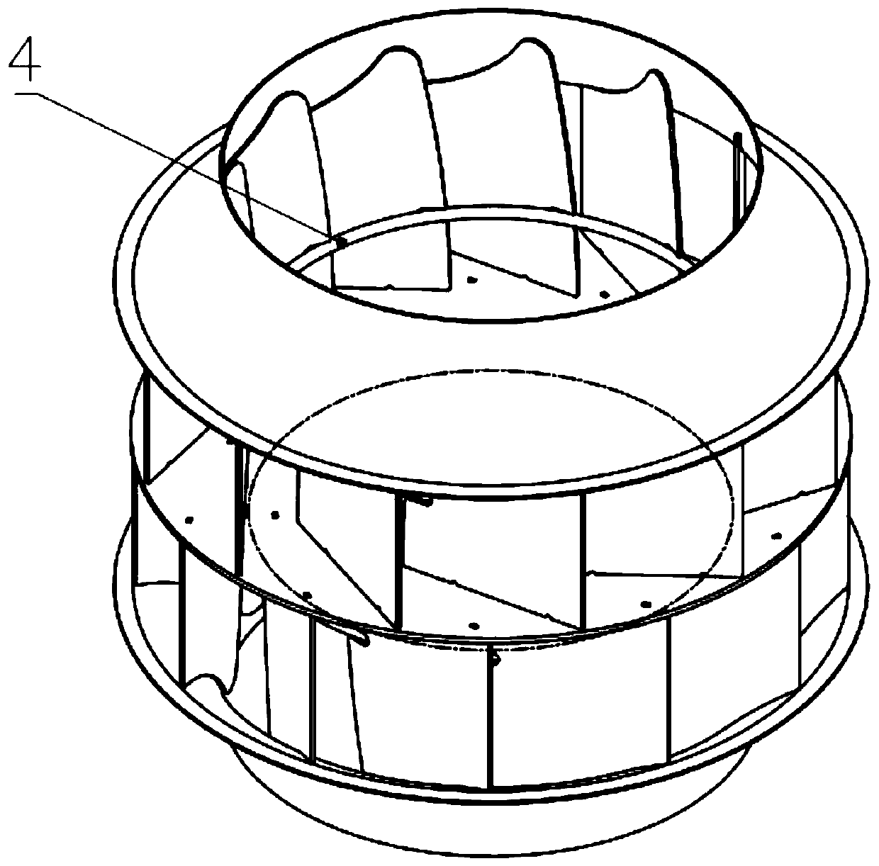
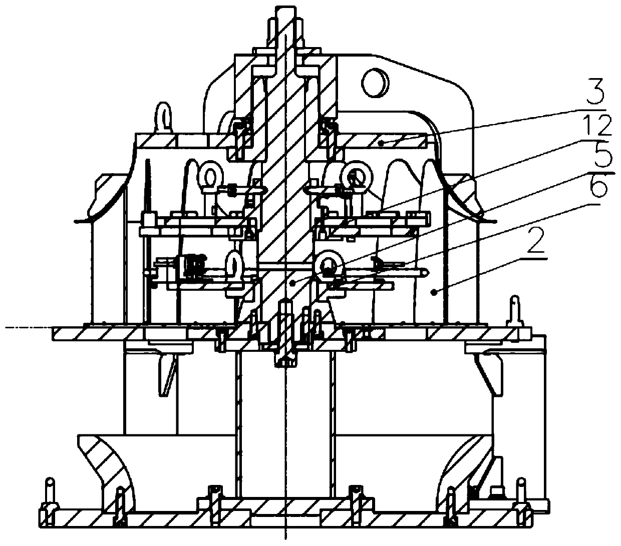
[0036] see Figure 1-16 , in an embodiment of the present invention, a carbon steel impeller assembly and welding device, including a main body assembly 7, a central shaft 8, a central support ring 9, a pressure plate 10, a cone centering assembly 11, an impeller orientation assembly assembly 12, and a main body reverse assembly 13 and the impeller orientation group reverse assembly 14; the main body assembly 7 includes a bottom plate 15, a tray 16, a supporting plate 17, a lower column 18 and a spacer 19; the bottom plate 15 and the supporting plate 17 are distributed through several arrays The column 18 is connected, a tray 16 is provided between the bottom plate 15 and the supporting plate 17, and a spacer 19 is provided on the lower end of the tray 17; the central shaft 8 includes a central support 20, a positioning plate 21, and a diamond pin 22 , screw rod 23, connecting shaft 24; the upper end of the center support 20 is provided with a positioning plate 21, and the dia...


PUM


Abstract

The invention discloses a carbon steel impeller assembling and welding device, and a method. The carbon steel impeller assembling and welding device comprises a main body forward assembling device, acentral shaft, a central supporting ring, a compression plate, a conical plate centering component, an impeller directional group forward assembling device, a main body reverse assembling device and an impeller directional group reverse assembling device, wherein the main body forward assembling device comprises a bottom plate, a tray, a supporting plate, lower stand columns and a cushion block; the bottom plate and the supporting plate are connected through a plurality of lower stand columns subjected to array distribution; the tray is arranged between the bottom plate and the supporting plate; the lower end surface of the tray is provided with the cushion block; the central shaft comprises a central supporting device, a positioning plate, a rhombic pin, a threaded rod and a connecting shaft; and the upper end of the central supporting device is provided with a positioning plate. The carbon steel impeller assembling and welding device is convenient in operation and is quick and accurate in positioning, positioning accuracy is guaranteed through machine tool machining, 12 groups of blades are separated in one time through a forward rotation blade reference side positioning group and a reverse rotation blade compaction group for positioning, stripping is quick, and production efficiency is improved.

Description

technical field [0001] The invention belongs to the technical field of automatic welding, and relates to an assembly welding device, in particular to a carbon steel impeller assembly welding device and method. Background technique [0002] The traditional carbon steel impeller is assembled and welded by welding one group of blades to the upper cone and the center disk respectively, and then welding the other group of blades to the lower cone and the center disk respectively. At present, the existing welding method of the impeller usually adopts manual welding, draw auxiliary lines on the center disk of the impeller, then weld the blades on the center disk one by one, and finally weld the upper and lower cone disks on the top of the blades, and weld the blades together. The first step is very important. The accuracy of blade welding will directly affect the quality of the entire impeller. However, the efficiency of manual blade welding is extremely low, and the welding accura...

Claims


Application Information

Patent Timeline
Patent Type & Authority Applications(China)
IPC IPC(8): B23K37/04
CPCB23K37/0435
Inventor 侯超杰胡振海张庆喜邢宇兵阎坤
Owner YANTAI WALU ROBOT AUTOMATION CO LTD
Learn More