
A steel wire rod heat treatment device

A technology for heat treatment devices and steel wire rods, applied in heat treatment furnaces, heat treatment equipment, furnaces, etc., can solve problems such as broken wires, high inventory pressure, and low area shrinkage

Active Publication Date: 2022-01-18
HUBEI LONGSKY COMM TECH
View PDF8 Cites 0 Cited by
  • Summary
  • Abstract
  • Description
  • Claims
  • Application Information

AI Technical Summary

Problems solved by technology

[0002] Wire rod is also called wire rod, which usually refers to small-diameter round steel in a coil. The diameter of the wire rod is in the range of 5-19 mm (usually 6-9 mm), and its lower limit is the minimum size of the hot-rolled steel section. Stressed steel wire has the characteristics of high tensile strength and yield strength, good plasticity, and low relaxation performance. It is widely used in the construction of cement products, bridges, nuclear power plants, high-rise long-span buildings, expressways, etc. 82B wire rod is used to produce high-strength prestressed steel wire. The raw material, its production and use has attracted more and more attention. There will be residual internal stress in the wire rod (such as 82B wire rod) just after rolling, and the hydrogen element in the steel has not escaped and diffused in time, and the reduction of area is low. If If it is drawn immediately, there will be broken wires, so it needs to be stored in the natural environment for a certain period of time to eliminate the internal stress, let the hydrogen element diffuse and escape, and the reduction of area will increase, and then draw again, but in mass production In the middle, because the products occupy the storage area and the inventory pressure is high, the production often needs to be stopped immediately after the first batch. The production of the next batch of wire rods can only be organized after the mechanical properties of the previous batch of wire rods pass the natural aging test and leave the factory. Both management and production have brought certain difficulties, and at the same time will occupy the working capital of the enterprise

Method used

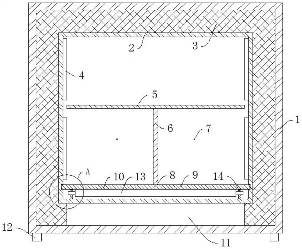
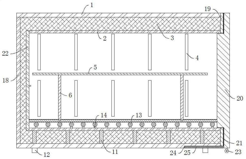

Image

  • A steel wire rod heat treatment device
  • A steel wire rod heat treatment device
  • A steel wire rod heat treatment device

Examples


Embodiment 1

[0023] refer to Figure 1-4 , a steel wire rod heat treatment device, comprising a second sleeve 2, a plurality of heating blocks 4 are fixedly connected to the inner wall of the second sleeve 2, the heating blocks 4 are connected to an external power supply, and one end of the second sleeve 2 is fixedly connected to a side plate 22, The outer side of the second sleeve 2 is covered with the first sleeve 1, and the bottom end of the first sleeve 1 is fixedly connected with a plurality of support legs 12, and the inner side of one end of the first sleeve 1 is fixedly connected with a sealing plate 18 at the opposite side plate 22. The bottom end of the sleeve 2 is fixedly connected with a number of first support blocks 11, and the end of the first support block 11 away from the second sleeve 2 is in contact with the inner side of the first sleeve 1. The side is fixedly connected with a return-shaped block 19, the inner side of the second sleeve 2 is fixedly connected with a numb...

Embodiment 2

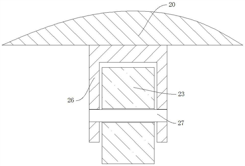
[0026] refer to image 3 , as another preferred embodiment of the present invention, on the basis of Embodiment 1, the rolling mechanism includes a concave block 26, a roller 23, and a roller shaft 27. One end of the concave block 26 is fixedly connected to the end cover 20, and the roller 23 is located in the concave In the groove of block 26, concave block 26 has turning hole relative to roller 23 axis places, turning hole concave block 26, roller 23, and roller 27 is positioned at turning hole, facilitates the movement of end cap 20 by roller 23.

Embodiment 3

[0028] refer to figure 2 , as another preferred embodiment of the present invention, on the basis of Embodiment 1, a guide rod 25 is fixedly connected to the bottom of one side of the end cover 20 relative to the return block 19, and the return block 19 is provided with a guide groove 24 relative to the guide rod 25, The guide groove 24 runs through the return-shaped block 19 and extends into the first sleeve 1, and the end of the guide rod 25 away from the end cover 20 is located in the guide groove 24, and the end cover 20 is relatively returned to the return-shaped block 19 through the guide groove 24 and the guide rod 25. move.


PUM


Abstract

The invention relates to the technical field of steel wire rod heat treatment equipment, in particular to a steel wire rod heat treatment device, which includes a second sleeve, a number of heating blocks are fixedly connected to the inner wall of the second sleeve, and a side plate is fixedly connected to one end of the second sleeve , the outer side of the second sleeve is covered with the first sleeve, and the inner side of one end of the first sleeve is fixedly connected with a sealing plate, and the bottom end of the second sleeve is fixedly connected with a plurality of first support blocks, and the first support blocks are far away from the first support block. One end of the second sleeve is in contact with the inner side of the first sleeve, and the same side of the first sleeve and the second sleeve is fixedly connected with a return-shaped block, and the inner side of the second sleeve is fixedly connected with a plurality of second support blocks. The two support blocks are rotatably connected with rollers, a placement plate is placed on the top of the rollers, an end cover is inserted inside the end of the second sleeve away from the side plate, a rolling mechanism is installed at the bottom of the end cover, and a temperature sensor is installed on one side of the side plate . The invention has a simple structure, can reduce the natural aging time of the steel wire rod, and is worth popularizing.

Description

technical field [0001] The invention relates to the technical field of steel wire rod heat treatment equipment, in particular to a steel wire rod heat treatment device. Background technique [0002] Wire rod is also called wire rod, which usually refers to small-diameter round steel in a coil. The diameter of the wire rod is in the range of 5-19 mm (usually 6-9 mm), and its lower limit is the minimum size of the hot-rolled steel section. Stressed steel wire has the characteristics of high tensile strength and yield strength, good plasticity, and low relaxation performance. It is widely used in the construction of cement products, bridges, nuclear power plants, high-rise long-span buildings, expressways, etc. 82B wire rod is used to produce high-strength prestressed steel wire. The raw material, its production and use has attracted more and more attention. There will be residual internal stress in the wire rod (such as 82B wire rod) just after rolling, and the hydrogen elemen...

Claims


Application Information

Patent Timeline
Patent Type & Authority Patents(China)
IPC IPC(8): C21D9/52C21D1/30
CPCC21D9/525C21D1/30
Inventor 杜子武刘连红杨民新高忠亮裴雷雷李宇凌
Owner HUBEI LONGSKY COMM TECH
Learn More