Double-layer continuous pipe double-gradient drilling system

A coiled tubing, dual gradient technology, applied in drilling equipment, subsea drilling, drilling pipes, etc., can solve the problems of high drilling safety risk, poor wellbore stability, narrow safety pressure window, etc. Effective control of bottom pressure and the effect of widening the density window

Pending Publication Date: 2020-04-17
SOUTHWEST PETROLEUM UNIV
View PDF1 Cites 12 Cited by
  • Summary
  • Abstract
  • Description
  • Claims
  • Application Information

AI Technical Summary

Problems solved by technology

However, when drilling in deep sea areas, there are problems such as narrow safety pressure window, weak cementation of the seabed formation, difficulty in wellbore pressure control and poor wellbore stability, resulting in high drilling safety risks and high costs

Method used


Image

  • Double-layer continuous pipe double-gradient drilling system
  • Double-layer continuous pipe double-gradient drilling system
  • Double-layer continuous pipe double-gradient drilling system

Examples


Embodiment 1

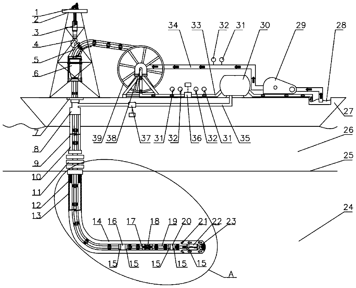
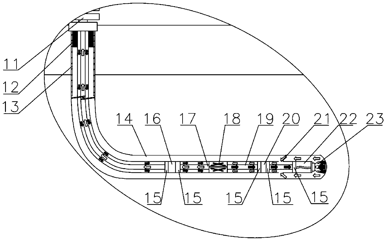
[0028] Such as Figure 1-3 As shown, this embodiment provides a double-layer coiled tubing dual-gradient drilling system, including a double-layer coiled tubing system, a drilling fluid circulation system, and a downhole lift pump system. The double-layer coiled tubing system and the drilling fluid circulation system are installed on the drilling ship 27; the double-layer coiled tubing system includes a double-layer coiled tubing 5, a drum 29, a double-layer coiled tubing injection head 6 and a conversion joint 38, and the double-layer coiled tubing 5 includes a continuous outer tube and a continuous tube fixed inside the continuous outer tube by an adjustment sleeve. An annular channel is formed between the inner pipe, the continuous outer pipe and the continuous inner pipe. The top of the double-layer continuous pipe 5 is wound on the rotating shaft of the drum 39 and connected to the drilling fluid circulation system through the conversion joint 38. The drum 39 is used for l...

Embodiment 2

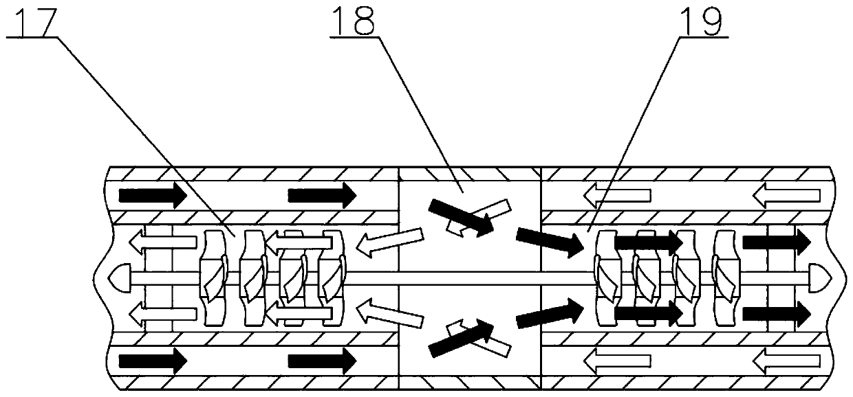
[0050] like Figure 4 As shown, the present embodiment provides a double-layer coiled tubing dual-gradient drilling system, wherein the driving component is preferably a motor 41. When the lift pump 17 uses the motor 41 instead of the hydraulic motor 19 to provide power, its power is passed through the cable 40 or The supply of the double-layer coiled tubing 5 with an insulating layer can reduce the energy consumption of the drilling fluid 14 before reaching the bottom of the well, and reduce the burden on the drilling pump group 29 .

[0051] Other structures of this embodiment are the same as those of Embodiment 1, and will not be repeated here.


PUM


Abstract

The invention discloses a double-layer continuous pipe double-gradient drilling system. On the basis of conventional drilling equipment, the double-layer continuous pipe double-gradient drilling system includes a double-layer continuous pipe system, isolation fluid, a downhole lifting pump system, a throttle control system and a data monitoring system; power fluid is injected by a drilling pump package, passes through a conversion joint and enters a double-layer pipe annulus, passes through a downhole lifting pump, enters a double-layer continuous pipe inner pipe through a bridge type channel,and then passes through a power drill tool and a drill bit and enters a bottom hole; and return fluid passes through a recovery hole and enters an annulus channel of a double-layer continuous pipe, then enters the double-layer continuous pipe inner pipe through the bridge type channel and enters the downhole lifting pump, and then passes through the conversion joint and the throttle control system successively and enters a solid control system. According to the double-layer continuous pipe double-gradient drilling system, a drill pipe does not need to be connected, the drilling time is saved,through monitoring of the isolation fluid and adjustment and control of the drilling pump package, the bottom hole pressure gradient is adjusted and controlled, the problem of narrow safety drillingdensity windows is solved, the advantages of lowering the drilling cost, reducing the drilling risk, and improving the efficiency are achieved, and the practicability is high.

Description

technical field [0001] The invention relates to the field of deep water drilling, in particular to a double-layer continuous tubing double-gradient drilling system. Background technique [0002] At present, the global energy problem is becoming more and more serious, and the oil and gas resources in land and shallow sea areas are far from meeting the needs of human beings. The exploration and development of deep-water oil and gas resources has become a current development hotspot. However, when drilling in deep sea areas, there are problems such as narrow safety pressure window, weak cementation of the seabed formation, difficulty in wellbore pressure control, and poor wellbore stability, resulting in high drilling safety risks and high costs. [0003] Therefore, in order to promote the exploration and development of deep-water offshore oil and gas, how to address the problems of easy-to-leak production layers, poor drilling safety in loose seabed surface layers, low format...

Claims


Application Information

Patent Timeline
Patent Type & Authority Applications(China)
IPC IPC(8): E21B7/12E21B17/20E21B17/01E21B17/08E21B19/22E21B21/08E21B21/01E21B47/00F04B47/06F04B17/03F04B17/00B63B35/44
CPCB63B35/4413E21B7/12E21B17/01E21B17/085E21B17/20E21B19/22E21B21/01E21B21/08E21B47/00F04B17/00F04B17/03F04B47/06
Inventor 钟林王国荣刘清友周守为余兴勇李中唐洋付强黄鑫李炎军刘和兴
Owner SOUTHWEST PETROLEUM UNIV
Why Eureka
Try Eureka