Bottle pattern baking furnace

A baking furnace and furnace body technology, which is applied in the field of bottle body decal baking furnace, can solve the problems such as the influence of bottle body processing quality, and achieve the effect of stable decal pattern, long retention time and not easy to scratch

Active Publication Date: 2020-04-17
重庆德立玻璃制品有限公司
View PDF5 Cites 0 Cited by
  • Summary
  • Abstract
  • Description
  • Claims
  • Application Information

AI Technical Summary

Problems solved by technology

[0003] The present invention intends to provide a bottle body decal baking furnace to solve the technical problem in the prior art that volatile substances stay in the furnace for a long time and cause adverse effects on the processing quality of the bottle body

Method used


Image

  • Bottle pattern baking furnace
  • Bottle pattern baking furnace
  • Bottle pattern baking furnace

Examples


Embodiment 1

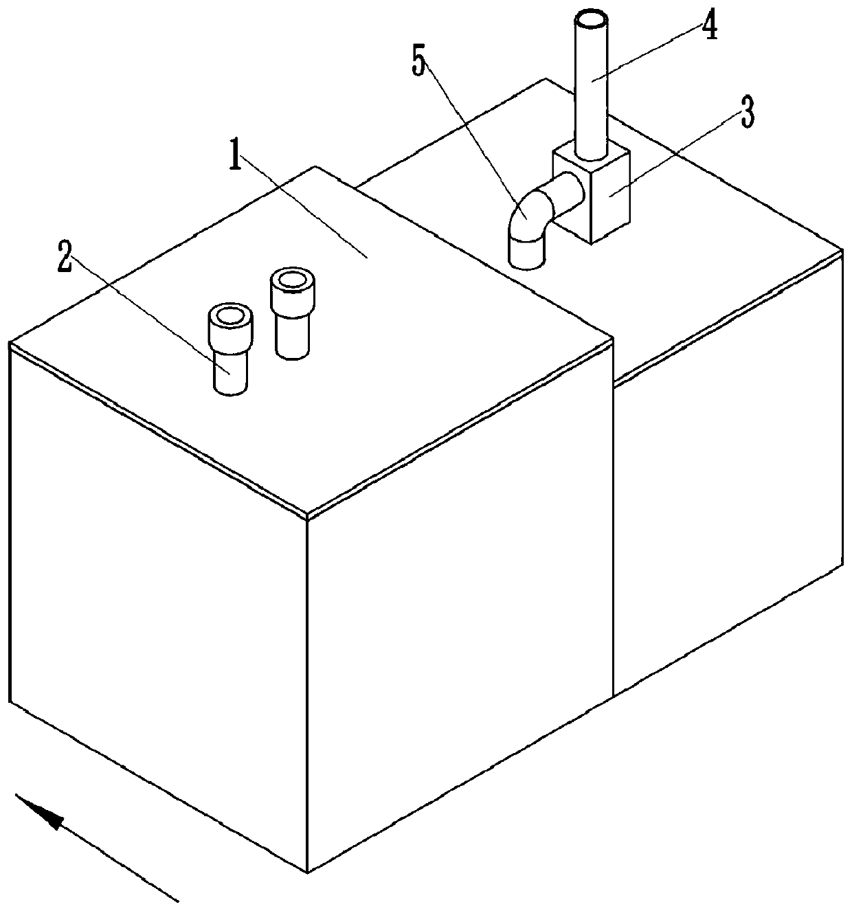
[0035] as attached figure 1 Shown: a bottle decal baking furnace, including a high-temperature furnace body 1, the high-temperature furnace body 1 is provided with an air inlet and an exhaust port, the air inlet is connected with an air inlet pipe 2, and the air inlet pipe 2 is glued inside A filter device for filtering granular impurities is fixedly provided, and the filter screen 8 is taken as an example here.

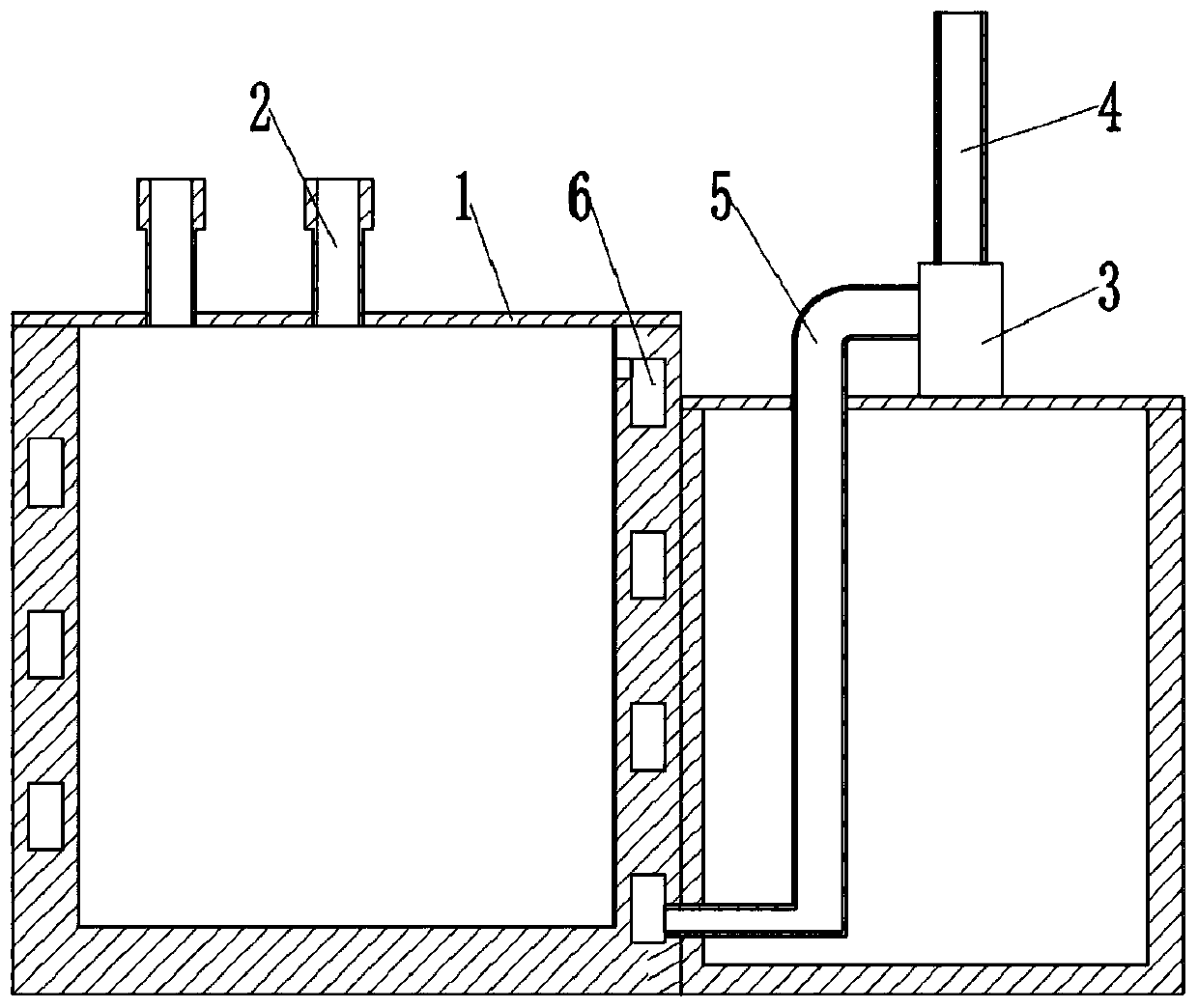
[0036] Such as figure 2 As shown, the side wall of the high-temperature furnace body 1 is provided with a circulation channel 6, and the circulation channel 6 is spirally arranged around the high-temperature furnace body 1. The gas outlet end of 6 is located at the lower part of the high temperature furnace body 1; the inlet end of the circulation channel 6 communicates with the interior of the high temperature furnace body 1, the gas outlet end of the circulation channel 6 communicates with the exhaust port through the exhaust pipe 5, and the exhaust port passes t...

Embodiment 2

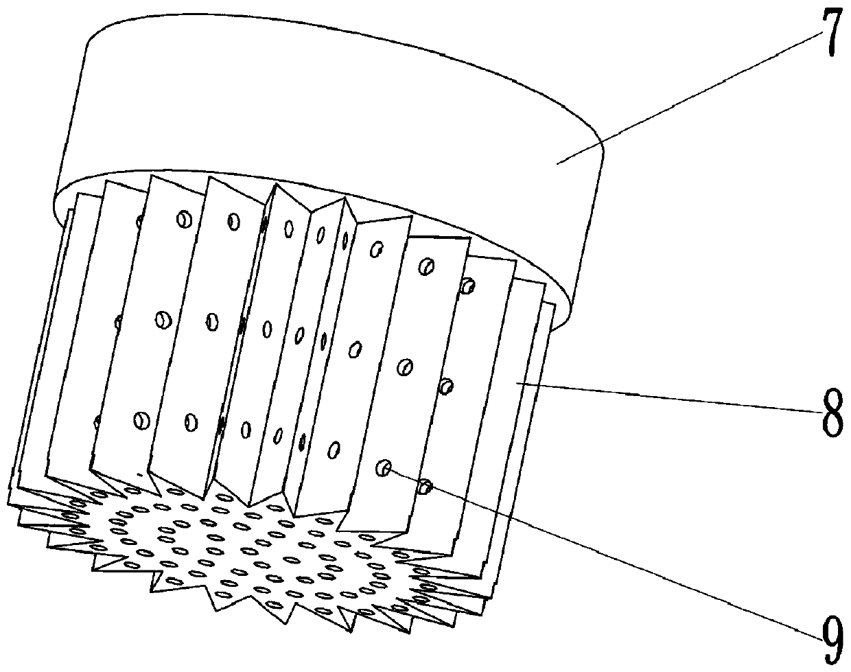
[0040]Such as image 3 As shown, the difference between this embodiment and Embodiment 1 is that the filter device includes a snap ring 7 and a filter screen 8 fixed to each other, the filter screen 8 is located in the middle of the snap ring 7 and completely covers the hollow part of the snap ring 7, and the filter screen 8 is a concave structure, the edge of the filter screen 8 is embedded in the snap ring 7 and fixed with the snap ring 7, and the peripheral wall of the filter screen 8 is a uniformly distributed fold shape; as Figure 4 , Figure 5 As shown, the air intake pipe 2 is provided with an installation chute 10 in the axial direction, and the snap ring 7 is slidably connected with the air intake pipe 2 through the installation chute 10 .

[0041] The snap ring 7 and the air intake pipe 2 of this program are connected through the installation chute 10, which is convenient for the installation or replacement of the filter device, and the snap ring 7 can be directly ...

Embodiment 3

[0043] Such as Figure 6 As shown, the difference between the present embodiment and the second embodiment is that a cylinder 11 is fixedly connected with a bolt in the chute 15, and the piston rod of the cylinder 11 is clamped and fixed with the upper end of the snap ring 7; between the snap ring 7 and the intake pipe 2 Also be provided with cleaning mechanism, cleaning mechanism comprises connecting rod 13, scraper 14 and the motor that drives connecting rod 13 to rotate, here is example with stepper motor 12, and stepper motor 12 is fixedly connected with crossbar 20 by bolt, crossbar 20 The clamping is fixedly arranged on the inner peripheral wall of the air inlet duct; the line of the stepper motor 12 is communicated with a key switch 18, and the key switch 18 is fixed on the top of the chute 15 by bolts, and the snap ring 7 can be Squeeze with the key switch 18; the output shaft of the stepper motor 12 is coaxially fixedly clamped with the connecting rod 13, and the lowe...


PUM


Abstract

The invention relates to the technical field of bottle patterns, and discloses a bottle pattern baking furnace. The bottle pattern baking furnace comprises a high-temperature furnace body, wherein thehigh-temperature furnace body is provided with an air inlet port and an air exhaust port, the air exhaust port communicates with a draught fan, and the draught fan is fixed to the high-temperature furnace body. The side wall of the high-temperature furnace body is provided with a circulation channel, wherein the air inlet end of the circulation channel communicates with the high-temperature furnace body, and the air outlet end of the circulation channel communicates with the air exhaust port. According to the technical scheme, the technical problem in the prior art that volatile substances are retained in the furnace for a long term, and the processing quality of bottles is affected can be solved.

Description

technical field [0001] The invention relates to the technical field of bottle body decals, in particular to a bottle body decal baking furnace. Background technique [0002] After the decals are applied on the bottle body, it needs to be sent into a decal furnace to roast and solidify the decal patterns to obtain a wine bottle with decals on the surface. During the baking process, volatile substances diffuse in the furnace. If they stay in the furnace for a long time, too much harmful substances will be attached to the bottle body, which will affect the processing quality of the glass bottle; and the inner wall of the furnace body and the furnace body The long-term operation of other internal structures is likely to generate waste debris, and the waste debris attached to the bottle body will easily cause flaws in the decal pattern, resulting in unsatisfactory hygienic conditions of the bottle body. Contents of the invention [0003] The present invention intends to provid...

Claims


Application Information

Patent Timeline
Patent Type & Authority Applications(China)
IPC IPC(8): F27B17/00F27D17/00F27D7/04
CPCF27B17/0041F27D7/04F27D17/002F27D17/008F27D2007/045F27M2003/08
Inventor 高青林
Owner 重庆德立玻璃制品有限公司
Why Eureka
Try Eureka