
A single-frame dynamic three-dimensional measurement method

A three-dimensional measurement and dynamic technology, applied in measuring devices, image analysis, image enhancement, etc., can solve the problems of non-negligible time interval, inability to obtain absolute phase, phase measurement error, etc.

Active Publication Date: 2021-05-14
XIDIAN UNIV
View PDF6 Cites 0 Cited by
  • Summary
  • Abstract
  • Description
  • Claims
  • Application Information

AI Technical Summary

Problems solved by technology

Since multiple frames of fringe images are required to extract the phase of the object, it is difficult to achieve high-speed three-dimensional measurement; when measuring a moving object, the phase shift between the captured fringe images of the moving object is not uniform, which will lead to phase measurement errors; in addition, when When the object is moving, the time interval between frames cannot be ignored, so it will not be possible to capture the motion information of the object between frames, and then the absolute phase will not be obtained and the phase blur will appear. At this time, a large number of additional stripes are required for time phase expansion. to remove blurring, so real-time 3D measurement cannot be achieved
[0004] Single-frame methods, such as Fourier profilometry, only require one frame of fringe images to extract the phase information of the object. This method has advantages in fast measurement, but it is usually very sensitive to noise and surface texture changes and due to spectral loss. The reconstruction accuracy is not high

Method used


Image

  • A single-frame dynamic three-dimensional measurement method
  • A single-frame dynamic three-dimensional measurement method
  • A single-frame dynamic three-dimensional measurement method

Examples


Embodiment 1

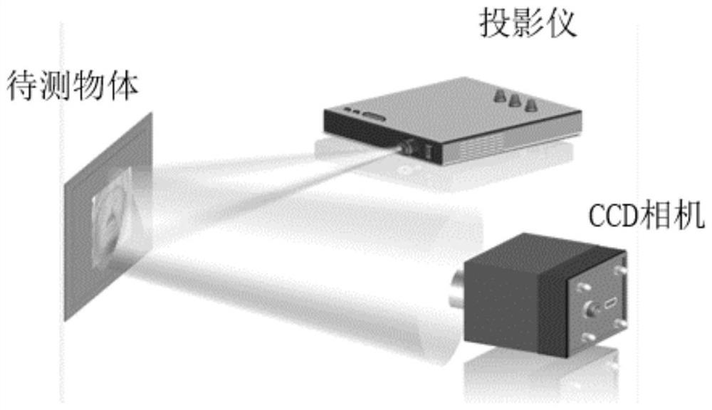
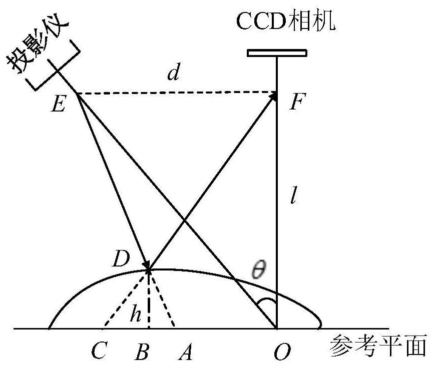
[0076] Please refer to figure 1 and figure 2 , figure 1 is a schematic structural diagram of a three-dimensional measurement system provided by an embodiment of the present invention, figure 2 It is the measurement schematic diagram of the three-dimensional measurement system provided by the embodiment of the present invention. As shown in the figure, the measurement principle of the three-dimensional measurement system is to use a projector to project stripes onto the surface of the object to be measured. The change in the shape of the object to be measured causes the stripes to be deformed. The phase information of the object is extracted, and the three-dimensional shape information of the object is obtained according to the phase-height mapping relation.

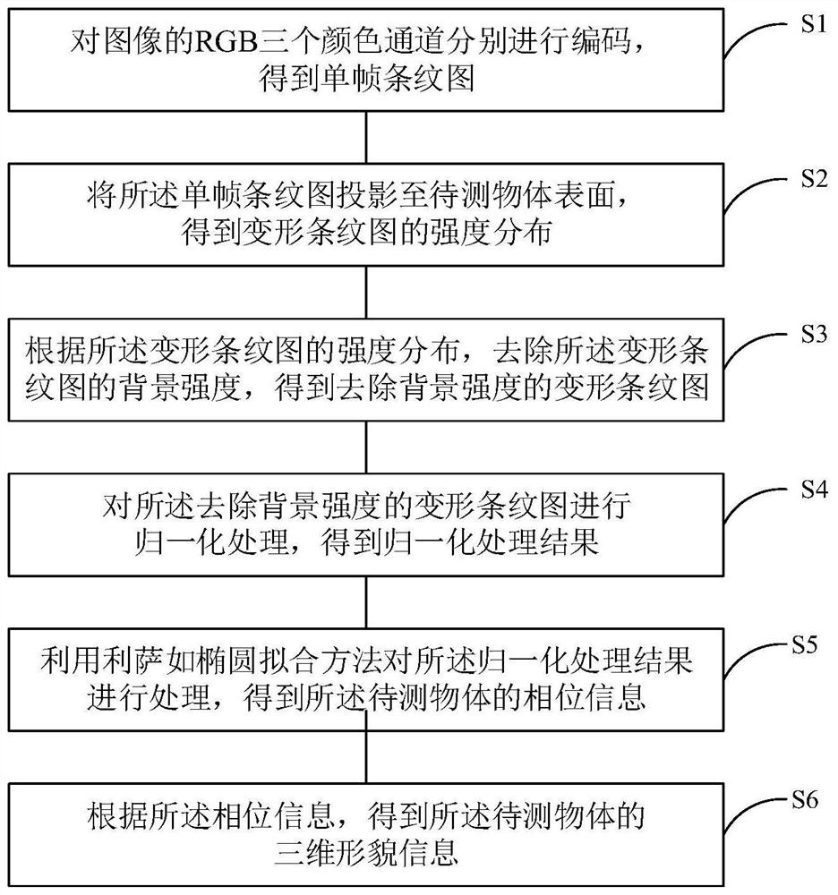
[0077] See image 3 , image 3 It is a flowchart of a single-frame dynamic three-dimensional measurement method provided by the embodiment of the present invention. As shown in the figure, the single-frame dynamic ...

Embodiment 2

[0139] This embodiment is a comparative simulation test of the single-frame dynamic three-dimensional measurement method of the first embodiment, the four-step phase shift method, and the Fourier profilometry measurement method to illustrate that the method of the present invention has higher robustness and accuracy .

[0140] The reference phase provided by this embodiment is Its size is 801×801, see Figure 4 and Figure 5 , Figure 4 and Figure 5 is a reference phase diagram provided by the embodiment of the present invention, where Figure 4 is the phase diagram of the reference phase, Figure 5 is a top view of the reference phase.

[0141] In this embodiment, the phase shift between the R color channel and the B color channel of the single-frame fringe image is set to In order to verify that the object to be tested has different reflectances for the R color channel and the B color channel, the background intensity and contrast of the R color channel and the B c...


PUM


Abstract

The present invention involves a single -frame dynamic three -dimensional measurement method, including: the three color channels of the RGB of the image are encoded separately to obtain a single -frame striped diagram; projected the single -frame stripe picture to the surface of the object to obtain the strength of the deformation striped diagram.Distribution; according to the intensity distribution of the deformation striped graph, remove the background strength of the deformed stripe map, to obtain a deformed stripe diagram that removes the background strength; the deformation striped diagram that removes the background intensity is normalizedThe Saru oval fitting method is processed to the normalization of the normalization of the normalization to obtain the phase information of the object to be tested; according to the phase information, the three -dimensional form information of the object to be tested is obtained.The method of the present invention applies the phase information of Lisa such as ellipsoid fitting technology to the striped projection system. It can be rebuilt the three -dimensional shape of the object with only a single -frame stripe. The calculation is easier.Robberry and accuracy.

Description

technical field [0001] The invention belongs to the technical field of three-dimensional measurement of objects based on fringe projection, and in particular relates to a single-frame dynamic three-dimensional measurement method. Background technique [0002] In the field of 3D object surface measurement, 3D object measurement technology based on fringe projection technology has been widely used in various fields, such as industrial detection, face detection, medical plastic surgery, etc., due to its low cost, high precision, high reliability and Non-contact has become one of the most commercialized and efficient methods in 3D object measurement technology. This technology uses a projector to project fringes onto the surface of the object to be measured. Changes in the shape of the object to be measured cause the fringe to deform. The fringe deformation is analyzed and the phase information of the deformed fringe pattern is extracted to obtain the height information of the o...

Claims


Application Information

Patent Timeline
Patent Type & Authority Patents(China)
IPC IPC(8): G01B11/25G06T7/90
CPCG01B11/254G06T2207/10024G06T7/90
Inventor 吴雨祥朱进进邵晓鹏李伟樊增增孙杨帆梁文海何顺福
Owner XIDIAN UNIV
Learn More