A Deep Sea Acoustic Launching Submersible

An acoustic and deep-sea technology, applied to buoys, instruments, special-purpose ships, etc., can solve problems such as high circuit power consumption, increase system complexity, and affect the difficulty of pressure-resistant structure design, achieving low power consumption, expanding the range of action, The effect of powerful computing power

Active Publication Date: 2020-09-08
INST OF ACOUSTICS CHINESE ACAD OF SCI
View PDF6 Cites 0 Cited by
  • Summary
  • Abstract
  • Description
  • Claims
  • Application Information

AI Technical Summary

Problems solved by technology

[0005] However, the traditional underwater acoustic launching submersibles mainly have the following two problems: First, the current launching submersibles generally have the problem of insufficient signal processing capability, and there are fewer types of transmitting signals, which are not easy to adjust, and do not have a signal source The ability of encoding and arbitrary signal generation is difficult to adapt to various needs in practical applications, and it does not have the feasibility of expanding applications
At the same time, the power consumption of the circuit used for signal processing and power amplification of the launching submersible is high, which seriously affects the underwater working time; the common method is to increase the scale of the energy battery pack, but this will increase the size and weight of the submersible and affect the endurance The design of the pressure structure is difficult, and it also increases the difficulty of laying and recovering the submersible tags. Therefore, the submersible tags need to reduce the power consumption of the system as much as possible under the premise of having a certain computing power.
Second, the traditional underwater acoustic launching submersibles are often restricted by energy conditions and working methods, and the range of action is small and the coverage is not enough. The first solution that comes to mind is to use multiple submersibles to work together. The collaboration ability between standards puts forward higher requirements. The most direct solution is to add two-way underwater acoustic communication equipment, but this will increase hardware overhead, increase system complexity, and bring a series of problems such as reliability and acoustic compatibility. technical problem

Method used


Image

  • A Deep Sea Acoustic Launching Submersible
  • A Deep Sea Acoustic Launching Submersible
  • A Deep Sea Acoustic Launching Submersible

Examples


Embodiment Construction

[0047] The present invention will be further described now in conjunction with accompanying drawing.

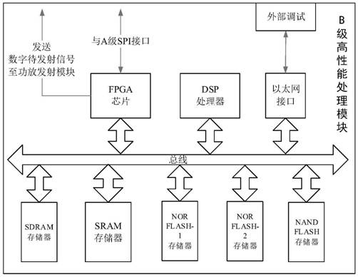
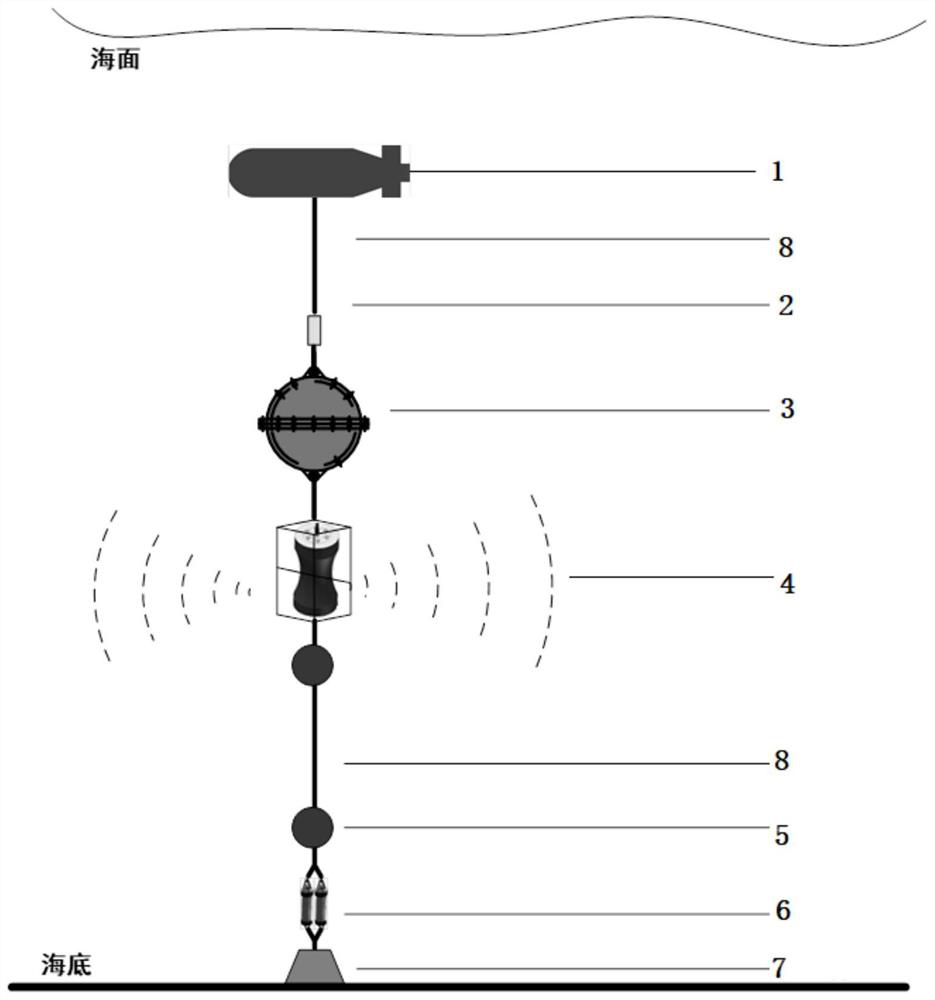
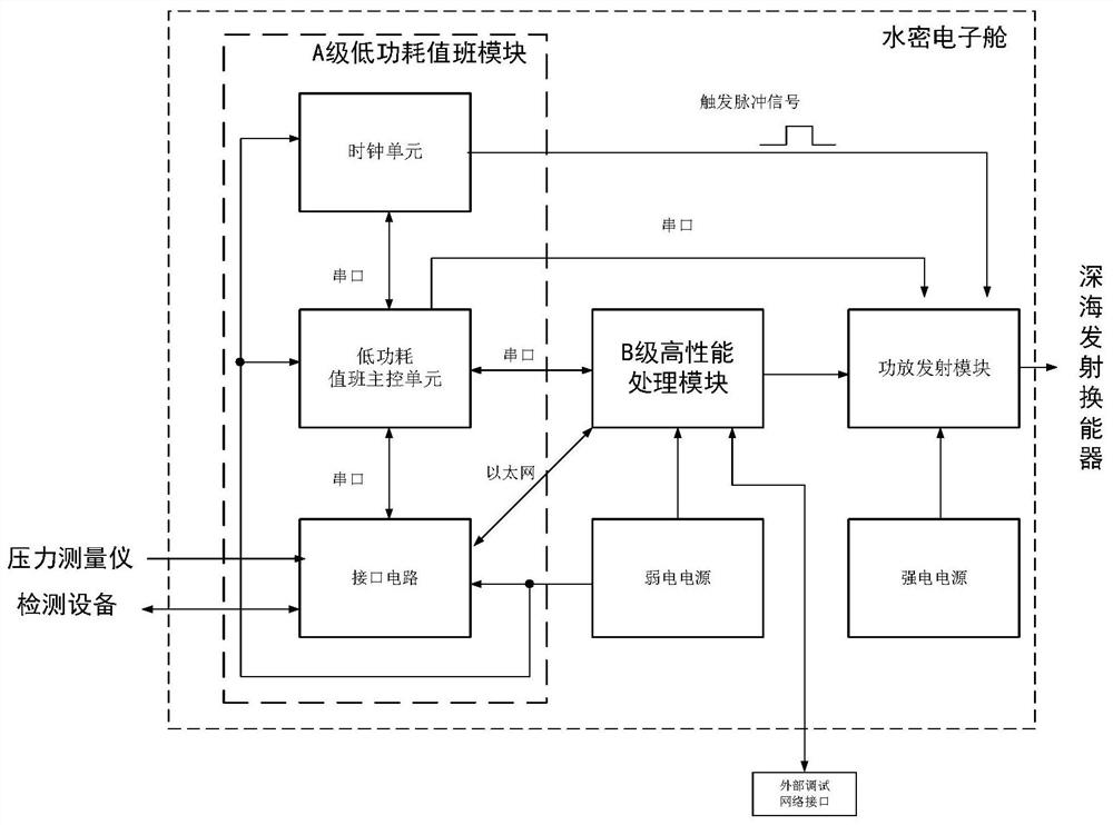
[0048] Such as figure 1 As shown, the present invention provides a deep-sea acoustic launching submersible, which includes a main buoy 1, a pressure measuring instrument 2, a watertight electronic cabin 3, a deep-sea launching transducer 4, a plurality of floating balls 5, and a deep-sea parallel connection connected in sequence. Acoustic releaser 6, mooring weight 7; wherein, a plurality of floating balls 5 are connected in series; mooring weight 7 is fixed on the seabed. Among them, the main floating body 1, the pressure measuring instrument 2, the watertight electronic cabin 3, the deep sea launch transducer 4, a plurality of floating balls 5, the deep sea parallel acoustic release device 6, and the mooring weight 7 are connected by Kevlar rope 8 .

[0049] The watertight electronic cabin is made of high-strength titanium alloy material, which is a spherical watertight s...


PUM


Abstract

The invention belongs to the technical field of ocean detection equipment, and particularly relates to a deep-sea acoustic emission subsurface buoy, which comprises a main floating body (1), a pressure measuring instrument (2), a watertight electronic cabin (3), a deep-sea emission transducer (4), a plurality of floating balls (5), a deep-sea parallel acoustic releaser (6) and an anchoring weight(7) which are connected in sequence, wherein the plurality of floating balls (5) are connected in series; the anchoring weight (7) is fixed at the seabed; the main floating body (1), the pressure measuring instrument (2), the watertight electronic cabin (3), the deep sea transmitting transducer (4), the floating balls (5), the deep sea parallel acoustic releaser (6) and the anchoring weight (7) are connected through Kevlar ropes (8).

Description

technical field [0001] The invention belongs to the technical fields of marine detection equipment, marine development and marine safety, and in particular relates to a deep-sea acoustic launching submersible. Background technique [0002] The submersible buoy has been widely used as an important marine survey equipment. The submersible buoy has good concealment, is not easy to be damaged, has a simple structure, is easy to deploy, has a high success rate of recovery, and can work underwater for a long time. Among them, acoustic submersible buoys are widely used in many fields such as marine survey, marine environment monitoring, underwater acoustic physics research, underwater acoustic communication, underwater positioning and navigation, and national marine security. [0003] The underwater acoustic launch submersible is a kind of underwater acoustic device placed in the sea that can actively transmit acoustic signals according to the set program. Cooperating with other ty...

Claims


Application Information

Patent Timeline
Patent Type & Authority Patents(China)
IPC IPC(8): G01C13/00G01S7/524B63B22/00B63B22/04G04R20/02G04F5/14H04B1/04
CPCB63B22/00B63B22/04B63B2022/006G01C13/00G01S7/524G04F5/14G04R20/02H04B1/04H04B2001/0408
Inventor 陈曦韩一丁王海斌吴立新汪俊
Owner INST OF ACOUSTICS CHINESE ACAD OF SCI
Why Eureka
Try Eureka