Method for obtaining power calibration model and terminal equipment

A power calibration and model technology, which is applied in the direction of electric power measurement, measurement device, and instrument by applying the square-law characteristics of circuit components, which can solve the problems of complex measurement process and inability to guarantee, reduce complexity and improve system measurement indicators. and performance effects

Active Publication Date: 2020-04-17
THE 13TH RES INST OF CHINA ELECTRONICS TECH GRP CORP
View PDF8 Cites 2 Cited by
  • Summary
  • Abstract
  • Description
  • Claims
  • Application Information

AI Technical Summary

Problems solved by technology

However, the existing technology can only verify the measurement performance of the system in the linear working area, and cannot guarantee the system output measurement indicators and performance when measuring power devices in a nonlinear state, and the measurement process is complicated

Method used


Image

  • Method for obtaining power calibration model and terminal equipment
  • Method for obtaining power calibration model and terminal equipment
  • Method for obtaining power calibration model and terminal equipment

Examples


Embodiment Construction

[0046] In the following description, specific details such as specific system structures and technologies are presented for the purpose of illustration rather than limitation, so as to thoroughly understand the embodiments of the present invention. It will be apparent, however, to one skilled in the art that the invention may be practiced in other embodiments without these specific details. In other instances, detailed descriptions of well-known systems, devices, circuits, and methods are omitted so as not to obscure the description of the present invention with unnecessary detail.

[0047] In order to illustrate the technical solutions of the present invention, specific examples are used below to illustrate.

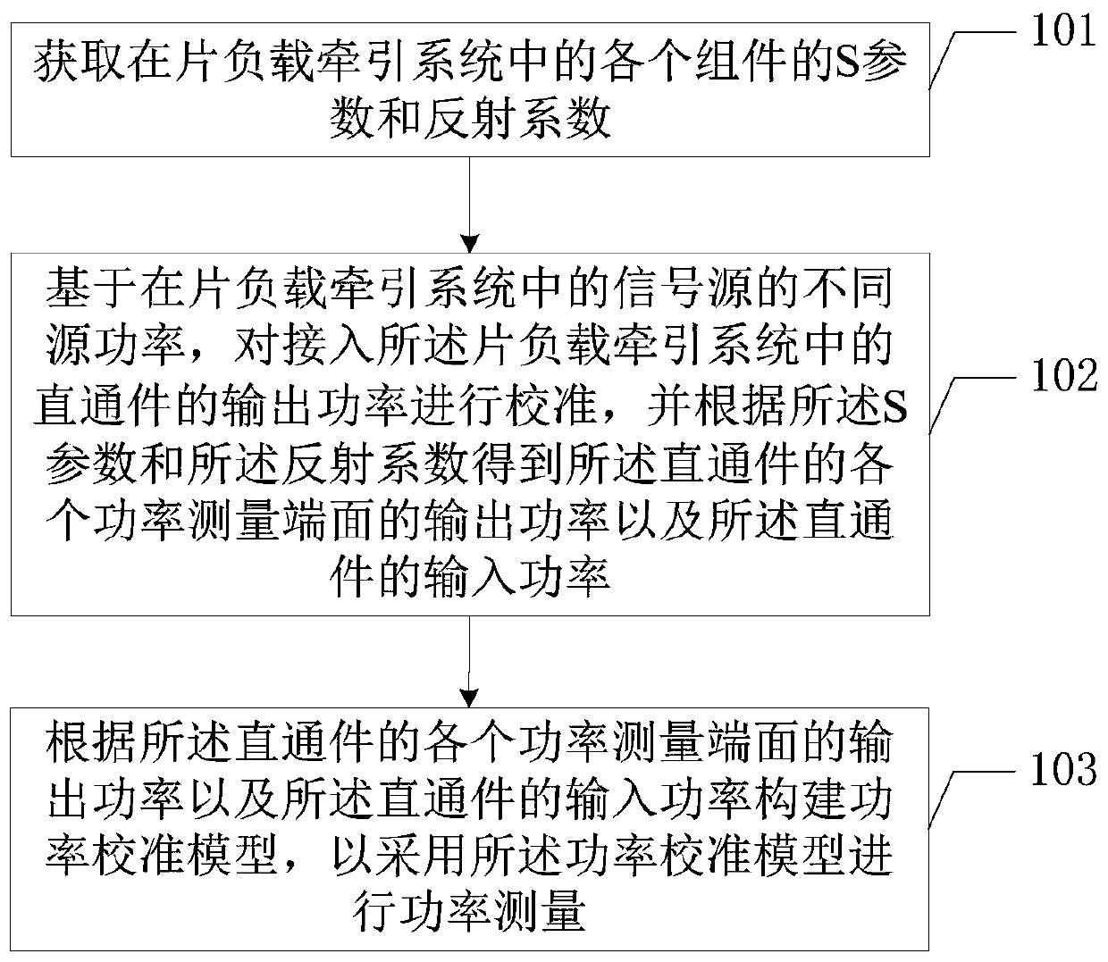
[0048] figure 1 It is a schematic flowchart of the implementation of the method for obtaining the power calibration model provided by the embodiment of the present invention, and is described in detail as follows.

[0049] Step 101, acquiring S-parameters and reflecti...


PUM


Abstract

The invention is suitable for the technical field of non-real-time on-chip load traction measurement, and provides a method for obtaining a power calibration model and terminal equipment. The method comprises the steps: obtaining an S parameter and a reflection coefficient of each assembly in an on-chip load traction system; based on different source powers of a signal source in the on-chip load traction system, calibrating the output power of a straight-through piece connected into the on-chip load traction system, and obtaining the output power of each power measurement end surface of the straight-through piece and the input power of the straight-through piece according to the S parameter and the reflection coefficient; constructing a power calibration model according to the output powerof each power measurement end surface of the straight-through piece and the input power of the straight-through piece; and using the power calibration model for power measurement, so that the outputpower can be calibrated before the output power is measured in a non-linear state. The system measurement index and performance during power device measurement can be improved, and the complexity of the measurement process is reduced.

Description

technical field [0001] The invention belongs to the technical field of non-real-time on-chip load pulling measurement, and in particular relates to a method for acquiring a power calibration model and a terminal device. Background technique [0002] When the on-chip load-pull measurement system performs output power measurement, it needs to perform self-calibration according to the prompt of the system measurement software. The self-calibration includes source power calibration measurement and S parameter calibration measurement. After the self-calibration is completed, the S parameter stored in the on-chip load-pull measurement system software is used for measurement, that is, the output power measured by the microwave power meter in the on-chip load-pull measurement system is calculated from the end face 4 to the output probe end face 2 of the DUT , so as to realize the output power measurement of the DUT under different load reflection coefficients. However, the existing...

Claims


Application Information

Patent Timeline
Patent Type & Authority Applications(China)
IPC IPC(8): G01R35/00G01R21/10
CPCG01R35/005G01R21/10
Inventor 栾鹏王一帮梁法国霍晔刘晨张立飞
Owner THE 13TH RES INST OF CHINA ELECTRONICS TECH GRP CORP
Why Eureka
Try Eureka