Depth estimation method based on binocular vision and laser radar fusion

A technology of laser radar and binocular vision, which is applied in the field of robot and computer vision, can solve the problems of inaccurate and inaccurate recovery of depth information, achieve good fusion results, strong flexibility, and improve robustness Effect

Pending Publication Date: 2020-04-17
ZHEJIANG UNIV
View PDF6 Cites 15 Cited by
  • Summary
  • Abstract
  • Description
  • Claims
  • Application Information

AI Technical Summary

Problems solved by technology

However, the results of semantic segmentation are not accurate in complex en...

Method used


Image

  • Depth estimation method based on binocular vision and laser radar fusion
  • Depth estimation method based on binocular vision and laser radar fusion
  • Depth estimation method based on binocular vision and laser radar fusion

Examples


Embodiment 1

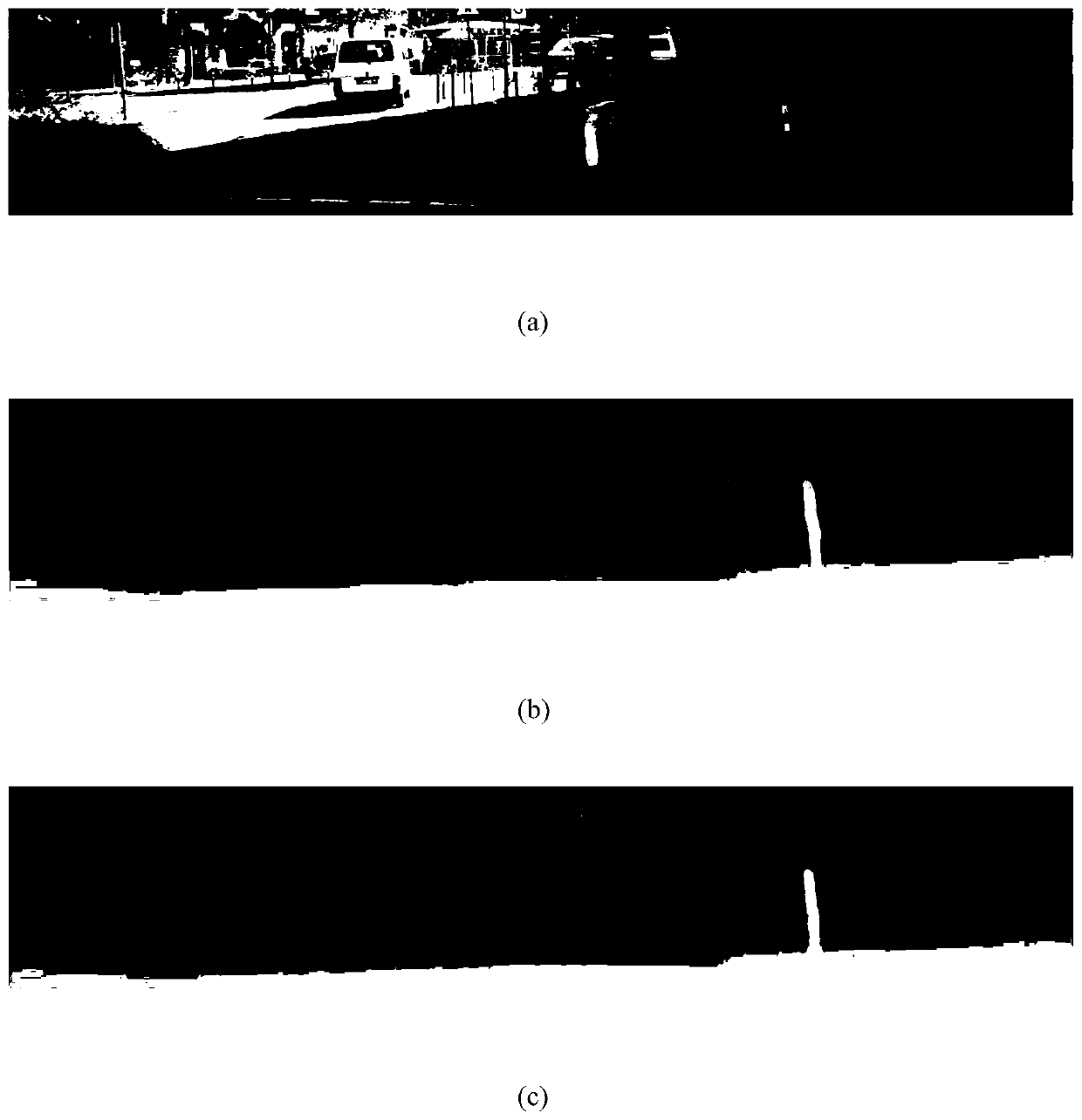
[0063] This embodiment mainly measures the pros and cons of the depth estimation quality in the road scene, mainly including the restoration of the details and the overall outline. figure 2 (a), (b), and (c) respectively represent the original graphics, the disparity map obtained by the PSMNet method and the disparity map obtained by the fusion of the method of the present invention. It can be seen from the results that, compared with the original binocular disparity map, the method of the present invention restores the contours of people and cars more accurately. At the same time, the original binocular disparity map has obvious errors in the depth estimation of distant poles, and there is a gap in the middle of them, but the method of the present invention estimates the depth information of the entire pole well.

Embodiment 2

[0065] This embodiment evaluates the method of the present invention through the Kitti2015 dataset. The Kitti2015 dataset consists of 200 sets of data, including left and right views and the corresponding ground truth. The corresponding lidar data can be obtained from the original data of Kitti. The data set compares the disparity map with the ground truth and calculates the error rate to evaluate the quality of the depth estimation. The lower the error rate, the better the quality of the depth estimation. The error rate is defined as the proportion of the number of pixels whose disparity value differs from the ground truth by more than 3 or more than 5% among all pixels. The specific results are shown in Table 1:

[0066] Table 1. Performance of each method on Kitti2015

[0067]

[0068] As can be seen from the table, the PSMNet method we used has an error rate of 3.98% on the Kitti2015 dataset. Afterwards, the result map obtained by PSMNet is fused, and the error rate ...


PUM


Abstract

The invention discloses a depth estimation method based on binocular vision and laser radar fusion. The method comprises the following steps: registering data acquired by a laser radar and a binocularcamera through joint calibration; obtaining a laser radar disparity map according to a joint calibration result; obtaining a binocular disparity map through a binocular stereo matching algorithm, performing confidence analysis on the binocular disparity map, removing points with low confidence in the binocular disparity map, and obtaining the binocular disparity map after confidence processing; performing feature extraction and fusion on the obtained laser radar disparity map and the binocular disparity map after confidence processing; carrying out further feature extraction and parallax regression through a cascade hourglass structure; adopting relay supervision to utilize output of front and back cascaded hourglass structures; and outputting an accurate and dense disparity map after fusion. According to the method, a more effective network structure is designed, the features of the laser radar disparity map and the binocular disparity map are better extracted and fused, and a more accurate disparity map is obtained.

Description

technical field [0001] The invention belongs to the application field of robot and computer vision, and in particular relates to a depth estimation method based on binocular vision and lidar fusion. Background technique [0002] In many robotics and computer vision applications, sensing the 3D geometry of a scene or object through depth estimation is undoubtedly the key to many tasks, such as autonomous driving, mobile robots, localization, obstacle avoidance, path planning, 3D reconstruction, etc. [0003] To estimate reliable depth information of the scene, two techniques can be used: depth estimation using a lidar scanner or stereo matching algorithms on binocular images. For complex outdoor scenes, lidar scanners are the most practical 3D perception solution. The 3D perception of lidar scanners can provide very accurate depth information with an error in centimeters. However, since the LiDAR point cloud is sparse and it accounts for less than 6% of the image points, rec...

Claims


Application Information

Patent Timeline
IPC IPC(8): G06T7/593G06T7/80G06T5/50
CPCG06T7/593G06T7/85G06T5/50G06T2207/10012G06T2207/10044G06T2207/10028G06T2207/20221G06T2207/20081G06T2207/20084
Inventor 陈昆沈会良
Owner ZHEJIANG UNIV
Why Eureka
Try Eureka