Parameter identification method for permanent magnet synchronous motor in steady-state operation mode

A permanent magnet synchronous motor, parameter identification technology, applied in the control of generator, motor generator control, AC motor control and other directions, can solve the problems of inconsistent identification results, voltage errors, sags, etc., to achieve inductance parameter identification results, The effect of suppressing torque ripple and improving identification accuracy

Active Publication Date: 2020-04-17
SOUTHEAST UNIV
View PDF14 Cites 16 Cited by
  • Summary
  • Abstract
  • Description
  • Claims
  • Application Information

AI Technical Summary

Problems solved by technology

[0004] At present, the main difficulties in the identification of motor parameters are as follows: the lack of rank of the identification equations leads to non-convergence of the calculation results, and the difficulty of nonlinear compensation of the inverter
For the low-rank problem of the identification equation, the existing solutions include: 1) Some parameters of the state equation of the fixed permanent magnet synchronous motor are design values ​​or offline identification values, and the identification results are obtained by step-by-step and multiple identification; 2) Injecting disturbances The signal is identified under the condition of the identification equation under the operating state of multiple sets of motors, and the disturbance signal is injected into the direct axis or the qua

Method used


Image

  • Parameter identification method for permanent magnet synchronous motor in steady-state operation mode
  • Parameter identification method for permanent magnet synchronous motor in steady-state operation mode
  • Parameter identification method for permanent magnet synchronous motor in steady-state operation mode

Examples


Embodiment Construction

[0040] Embodiments of the invention are described in detail below, examples of which are illustrated in the accompanying drawings. The embodiments described below by referring to the figures are exemplary only for explaining the present invention and should not be construed as limiting the present invention.

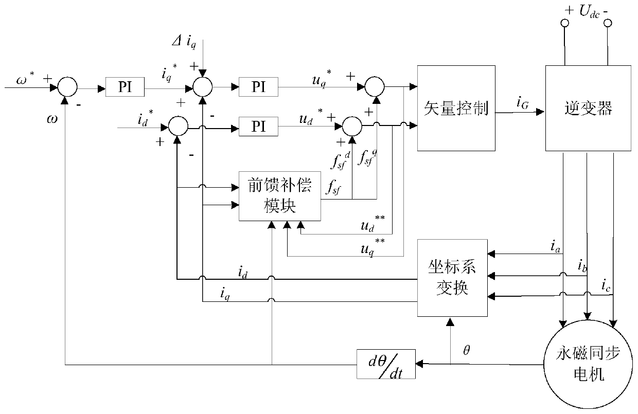
[0041] Such as figure 1 As shown, a parameter identification method for a permanent magnet synchronous motor in a steady state operation mode includes the following steps:

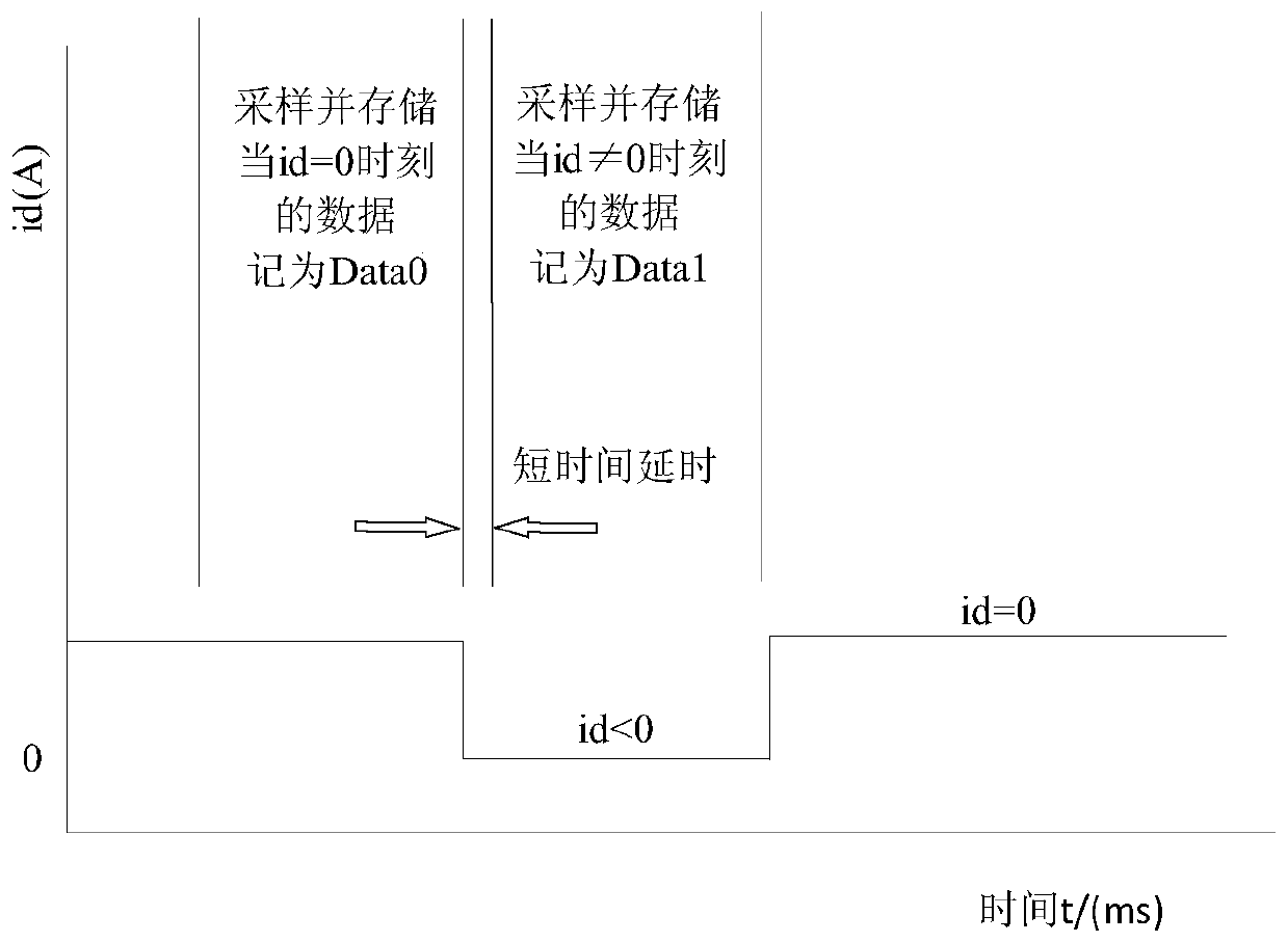
[0042] 1. When the motor is in a stable running state, the direct axis voltage u is obtained by sampling d , cross-axis voltage u q , direct axis current i d , quadrature axis current i q , motor electrical angular velocity ω e ; Direct axis injection short-time current Δi d (The present invention corresponds to the Δi of simulation injection d is -4A), re-sampled to extract the above five variables, and constructed a parameter identification equation. The principle of the identification metho...


PUM


Abstract

The invention discloses a parameter identification method for a permanent magnet synchronous motor in a steady-state operation mode. The method comprises the steps of: firstly carrying out sampling when the motor is in a steady-state operation state to obtain a direct-axis voltage, a quadrature-axis voltage, a direct-axis current, a quadrature-axis current and an electromechanical angular speed; after short-time current is injected into the direct axis, extracting the five variables again to construct a parameter identification equation; then, analyzing voltage error and three-phase current harmonic problems caused by nonlinearity of an inverter; setting the compensation time to adjust the on-off of a switch tube, reducing the nonlinear influence of the inverter, and improving the overallparameter identification precision; and finally, since the identification result of inductance depends on the direct-axis voltage to a great extent, further improving the identification precision of the inductance through a feedforward compensation algorithm. According to the method, the voltage error caused by the nonlinearity of the inverter can be effectively compensated, the content of the fifth and seventh harmonics of the three-phase current is obviously reduced, the resistance, inductance and permanent magnet flux linkage values can be identified more quickly and precisely, and the control performance of the permanent magnet synchronous motor is improved.

Description

technical field [0001] The invention relates to a parameter identification method for a permanent magnet synchronous motor in a steady-state operation mode, and belongs to the field of parameter identification of a permanent magnet synchronous motor. Background technique [0002] Permanent magnet synchronous motors have the characteristics of high operating efficiency, high starting torque, and high power (torque) density, and have been widely used in servo systems, electric vehicles, aerospace and other fields. [0003] First, considering that the resistance value and the amplitude of permanent magnet flux linkage change monotonously with the rise and fall of temperature, for example, as the temperature rises, the resistance value increases and the amplitude of permanent magnet flux linkage decreases. Therefore, the internal temperature of the motor can be monitored indirectly by observing the changes in the resistance value and the amplitude of the permanent magnet flux li...

Claims


Application Information

Patent Timeline
IPC IPC(8): H02P21/16H02P21/14H02P25/022
CPCH02P21/141H02P25/022H02P21/16
Inventor 张淦朱俊明花为程明
Owner SOUTHEAST UNIV
Why Eureka
Try Eureka