X-ray system and method for the operation thereof

An X-ray and X-ray tube technology, applied in the field of operating such X-ray systems, can solve the problems of long time required for inspection and great discomfort, and achieve short inspection duration, low beam load, and simple structure. Effect

Pending Publication Date: 2020-04-17
SIEMENS HEALTHCARE GMBH
View PDF6 Cites 3 Cited by
  • Summary
  • Abstract
  • Description
  • Claims
  • Application Information

AI Technical Summary

Problems solved by technology

Therefore, the time required for the inspection is relatively long, resultin...

Method used


Image

  • X-ray system and method for the operation thereof
  • X-ray system and method for the operation thereof
  • X-ray system and method for the operation thereof

Examples


Embodiment Construction

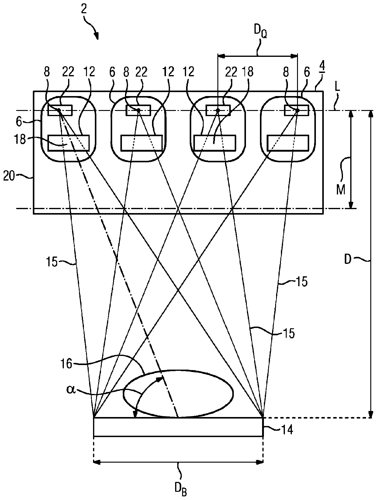
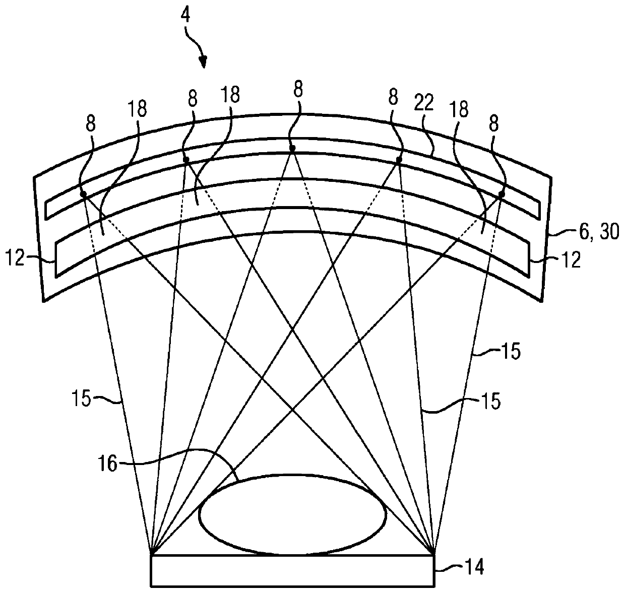
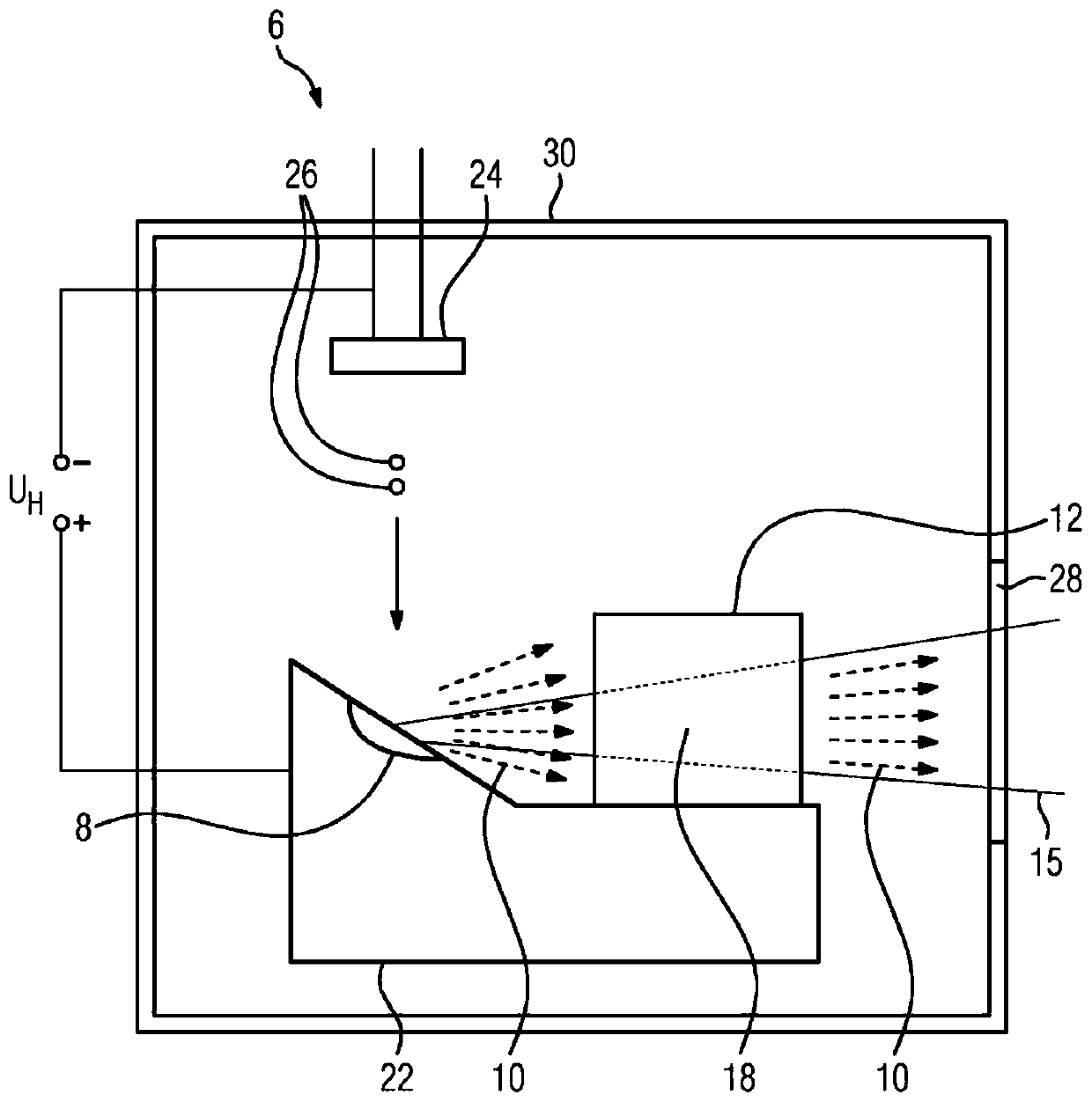
[0043] exist figure 1 shows an x-ray system 2 with an x-ray source 4 having a plurality of x-ray tubes 6 , of which only four x-ray tubes 6 are shown by way of example for a better overview. During operation, the x-ray tube 6 is activated sequentially, that is to say time-sequentially, by means of a control device not further shown, so that x-ray radiation is emitted at a time from only one x-ray focal spot 8 arranged in the x-ray tube 10( image 3 and Figure 4 ).

[0044] Here, the x-ray radiation 10 emitted from the x-ray focal spot 8 is each collimated by means of a collimator 12 to have a detector width D B on a detector 14 which is fixedly arranged with respect to the X-ray focal spot 8 . In other words, the x-ray radiation 10 not directed towards the detector is each suppressed by means of the collimator 12 associated with the corresponding x-ray focal spot 8 .

[0045] The x-ray radiation 10 directed at the detector 14 is generally shown as a beam 15 . In summary...


PUM


Abstract

The invention relates to an X-ray system (2) comprising an X-ray source (4) which generates X-ray radiation (10) at multiple X-ray focal spots (8) during operation, wherein each X-ray focal spot (8) is assigned a respective collimator (12), which selects the X-ray radiation (10) generated in the respective X-ray focal spot (8) and directed onto a common detector (14), wherein the collimators (12)are arranged such that they are stationary relative to their respective assigned X-ray focal spot (8), wherein the X-ray source (4) is configured as an X-ray tube (6) with at least one anode (22) having the X-ray focal spots (8) and with a number of cathodes (24), or wherein the X-ray source (4) has multiple X-ray tubes (6), the anodes (22) of which have the X-ray focal spots (8), and wherein thecollimators (12) are arranged in the respective X-ray tubes (6). The invention also relates to a method for operating an X-ray system (2) of this type.

Description

technical field [0001] The invention relates to an X-ray system having an X-ray source which generates X-ray radiation at a plurality of X-ray focal spots during operation, wherein each X-ray focal spot is separately connected to a quasi- Straighteners are associated. The invention also relates to a method for operating such an x-ray system. Background technique [0002] X-ray systems are used in medical examinations. In this case, the x-ray radiation is generated in the x-ray focal spot of the x-ray source and emitted from there. Subsequently, the x-ray radiation penetrates the object to be examined, wherein at least a portion of the x-ray radiation is absorbed by the object, and wherein the x-ray radiation produces an x-ray image on an especially digital detector. If a plurality of x-ray images (projections) of the object are recorded from different spatial angles (projection angles), a three-dimensional reconstruction of the object and image data can be created from th...

Claims


Application Information

Patent Timeline
IPC IPC(8): A61B6/00A61B6/06A61B6/02
CPCA61B6/025A61B6/06A61B6/4007A61B6/502G21K1/02H01J35/02H01J2235/08
Inventor 约尔格·弗罗伊登贝格尔彼得拉·莫雷尔
Owner SIEMENS HEALTHCARE GMBH
Why Eureka
Try Eureka