
Energy consumption self-recovery pressure type anchor rod and construction method thereof

A self-restoring, pressure-type technology, applied in the direction of foundation structure engineering, sheet pile walls, protection devices, etc., can solve the problems of residual strain that cannot be self-adjusted and recovered, and cannot effectively consume energy, etc., to achieve simple and feasible technology and improve the stress state , Ease of construction and installation

Active Publication Date: 2020-04-21
NINGXIA UNIVERSITY
View PDF8 Cites 6 Cited by
  • Summary
  • Abstract
  • Description
  • Claims
  • Application Information

AI Technical Summary

Problems solved by technology

[0003] The purpose of the present invention is to solve the problem that the traditional support structure cannot effectively dissipate energy when it is subjected to reciprocating loads and impact loads, and the residual strain cannot be self-adjusted and recovered after the load is over. Safety, propose an energy-consuming self-restoring pressure anchor and its construction method

Method used


Image

  • Energy consumption self-recovery pressure type anchor rod and construction method thereof
  • Energy consumption self-recovery pressure type anchor rod and construction method thereof
  • Energy consumption self-recovery pressure type anchor rod and construction method thereof

Examples


Embodiment Construction

[0043] The embodiments of the present invention will be described in detail below with reference to the accompanying drawings, but the present invention can be implemented in various ways defined and covered by the claims. Based on the embodiments of the present invention, all other embodiments obtained by persons of ordinary skill in the art without making creative efforts belong to the protection scope of the present invention.

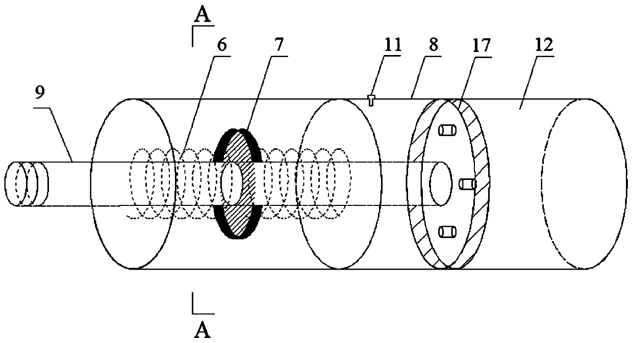
[0044]The present invention aims at the deficiency of the pressure-type anchor rod under the action of dynamic load, and proposes an energy-consuming self-restoring pressure-type anchor rod. The anchor rod has the function of yielding deformation, increasing the deformable displacement of the rod body during work, and the energy-consuming self-restoring device works It can effectively consume energy and buffer during the force transmission process of the anchor rod. After the load is over, the potential energy absorbed by the device can restore the d...


PUM

PropertyMeasurementUnit
diameteraaaaaaaaaa
diameteraaaaaaaaaa

Abstract

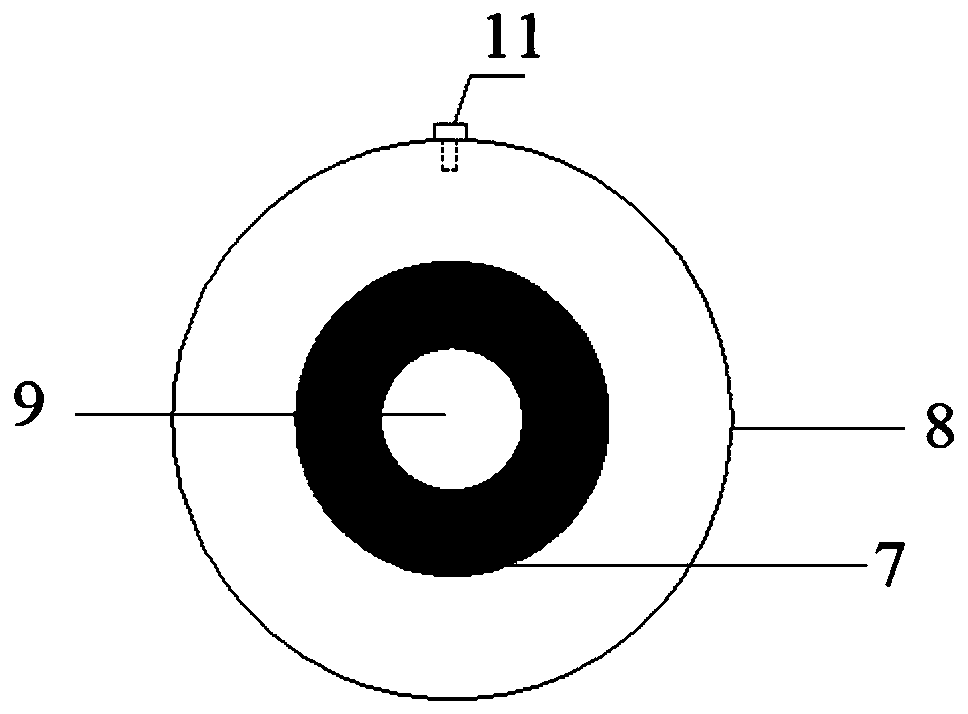
The invention provides an energy consumption self-recovery pressure type anchor rod and a construction method thereof. The pressure type anchor rod comprises an anchor rod system and an energy consumption self-recovery system. The anchor rod system comprises a rod body, a casing pipe, an anchorage device and a cushion plate. The front end of the anchor rod system is fixed to a soil retaining structure through the anchorage device and the cushion plate, the rear end of the anchor rod system is connected with the energy consumption self-recovery system, and slurry is injected to the periphery ofthe anchor rod system. The energy consumption self-recovery system comprises a hydraulic cylinder, springs, a baffle, a piston, a piston rod, viscous liquid, a throttling hole and a pressure bearingcylinder. The pressure bearing cylinder is connected with the front end of the hydraulic cylinder, and the cylinder is filled with the viscous liquid; one end of the piston rod is fixed to the piston,and the other end of the piston rod penetrates the hydraulic cylinder and the pressure bearing cylinder to be connected with the rod body; the baffle is arranged on the piston rod, and the two sidesof the baffles are sleeved with the springs; and under the impact and reciprocating load effect, the springs are pulled and pressed to drive the piston to move in the hydraulic cylinder, deformation yielding energy consumption and self recovery of the anchor rod are achieved, and the energy consumption and vibration reduction effects are obvious. The technology is simple and feasible, the self recovery device is arranged at the bottom of the anchor rod so that construction can be convenient, and the external slurry has a good protection effect.

Description

technical field [0001] The invention belongs to the technical field of rock-soil anchoring engineering, and in particular relates to an energy-consuming self-restoring pressure anchor rod and a construction method thereof, and is particularly suitable for impact-resistant support of slopes and underground engineering. Background technique [0002] In geotechnical engineering and underground engineering, bolt support has been widely used. The traditional pressure-type bolt can make the stress of the rod body pass to the end, and squeeze the grouting body through the pressure plate connected with the bolt, and further It is transmitted to the soil through the interface between the grout and the soil. Compared with the traditional tension anchor, the pressure anchor solves the problem of damage to the interface between the tendons and the grouting body, and has good anchoring ability. However, on November 18, 2019, a gas explosion in the roadway of Pingyao Coal Mine caused the...

Claims


Application Information

Patent Timeline
Patent Type & Authority Applications(China)
IPC IPC(8): E02D5/74E02D31/08
CPCE02D5/74E02D31/08E02D2200/14E02D2200/146E02D2300/0007E02D2300/0009E02D2300/0026E02D2600/30
Inventor 董旭光李峥雷肃孙国栋颉永斌田文通
Owner NINGXIA UNIVERSITY
Learn More