
Integral low-latency intermediate shaft brake
A technology of brakes and intermediate shafts, applied in the direction of axial brakes, brake types, brake components, etc., can solve the problems of transmission assembly assembly, inconvenient maintenance, long response time for releasing brakes, and difficulty in precise control, etc., to achieve Improve the convenience of assembly and maintenance, improve the response speed of the system, and have strong adaptability
- Summary
- Abstract
- Description
- Claims
- Application Information
AI Technical Summary
Problems solved by technology
Method used
Image

Examples
Embodiment Construction
[0023] Specific embodiments of the present invention will be described in detail below in conjunction with the accompanying drawings.
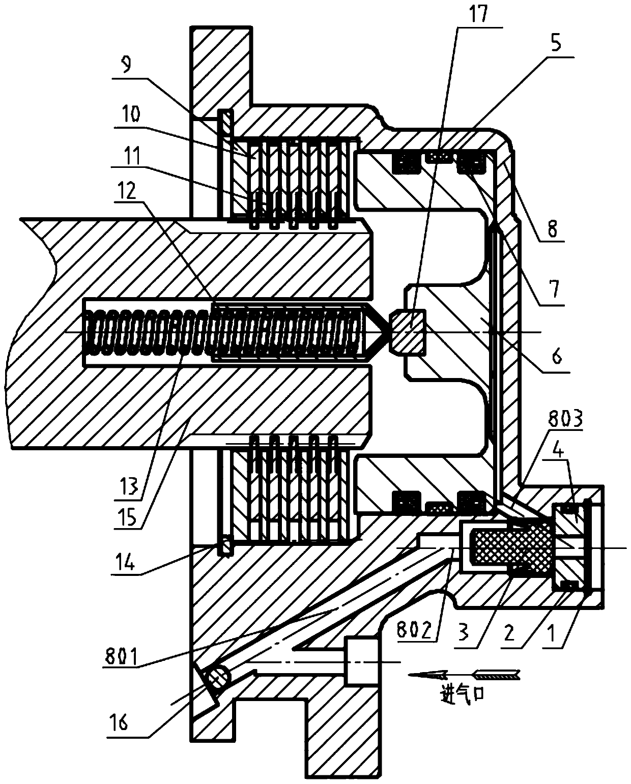
[0024] Such as figure 1 As shown, the brake is mounted on the front end of the intermediate shaft 15 of the transmission. The quick-release valve spool 3 is placed in the brake housing 8, and the brake housing 8 has an air circuit 801, an air circuit 802, and an air circuit 803. The steel ball 16 is used to block one end of the air circuit 801 so that it does not leak out. gas. The O-shaped sealing ring 2 is put into the ring groove of the exhaust plug 4 of the quick-release valve, and placed together in the brake housing 8, and the small snap ring 1 acts as a limiter. The ejector pin 17 is pressed into the piston 6, the guide ring 5 and two Y-shaped sealing rings 7 are installed in the ring groove of the piston 6, and the two Y-shaped sealing rings 7 are placed back to back and placed in the brake housing 8 together; The steel sheet 11 and...
PUM
 Abstract
Description
Claims
Application Information