Laminated quasi-optical feed network structure and adjusting method thereof

A network structure and stacking technology, applied in the direction of using optical devices, measuring electricity, measuring electrical variables, etc., to achieve the effect of solving the effect of electrical performance

Active Publication Date: 2020-04-21
SHANGHAI SPACEFLIGHT INST OF TT&C & TELECOMM
View PDF10 Cites 0 Cited by
  • Summary
  • Abstract
  • Description
  • Claims
  • Application Information

AI Technical Summary

Problems solved by technology

On the one hand, it solves the problem of assembly accuracy of a single quasi-optical component. On the other hand, it eliminates the cumulative assembly error through the combination of mechanical measurement and electrical performance testing, and realizes the micron-level assembly accuracy of the laminated quasi-optical feeding component.

Method used


Image

  • Laminated quasi-optical feed network structure and adjusting method thereof
  • Laminated quasi-optical feed network structure and adjusting method thereof
  • Laminated quasi-optical feed network structure and adjusting method thereof

Examples


Embodiment Construction

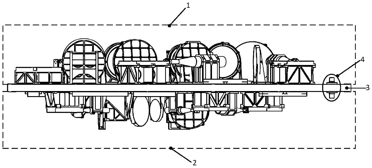
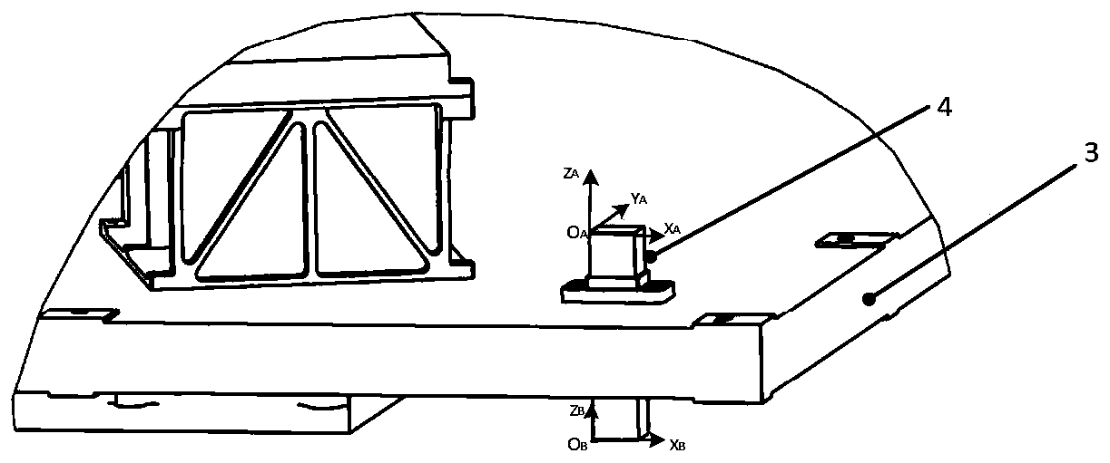
[0086] The following will combine Figure 1 to Figure 2 A method for detecting and adjusting the assembly accuracy of a laminated quasi-optical component provided by the present invention is described in detail. This embodiment is implemented on the premise of the technical solution of the present invention, and a detailed implementation mode and specific operation process are given. , but the scope of protection of the present invention is not limited to the following examples, those skilled in the art can modify and embellish it within the scope of not changing the spirit and content of the present invention.

[0087] The invention provides a method for detecting and adjusting the assembly accuracy of a laminated quasi-optical component, which mainly solves the problem of detecting and adjusting the assembly accuracy of a laminated quasi-optical feeding component. The composition of the laminated feed network is as follows: figure 1 As shown, it mainly includes the upper qu...


PUM


Abstract

The invention relates to a laminated quasi-optical feed network structure, which comprises a quasi-optical component mounting plate, an upper-layer feed system and a lower-layer feed system. The upper-layer feed system and the lower-layer feed system are arranged on the quasi-optical component mounting plate. Each of the upper-layer feed system and the lower-layer feed system at least comprises anellipsoidal mirror, a feed source horn, a frequency selective surface / polarization grid mesh and a plane mirror. The upper layer and the lower layer of the quasi-optical component mounting plate aresymmetrically provided with measuring reference pieces. The ellipsoidal mirror is provided with a measuring reference plane and at least one measuring reference hole. The frequency selective surface / polarization grid mesh is connected with the quasi-optical component mounting plate through a bracket; a mounting plane and a measurement reference hole are formed in the bracket According to the invention, for elimination of accumulated assembly errors of the laminated quasi-optical feed network system, the included angle between the mechanical axis direction and the electrical axis direction of each frequency band is calculated according to the planar near-field electrical performance test result of each frequency band link, and correction is carried out by adjusting the direction and orientation of a feed source horn by means of a multi-degree-of-freedom feed source horn adjusting and supporting tool.

Description

technical field [0001] The invention relates to the technical field of testing and adjusting the assembly accuracy of quasi-optical feeding components, in particular to a laminated quasi-optical feeding network structure and an adjusting method thereof. Background technique [0002] In order to meet the requirements of time and space resolution for practical applications, geostationary orbit detection needs to work in the microwave high frequency band. And the sounder is a multi-frequency, multi-polarization radiometer system. The purpose is that the sounder can simultaneously collect observation data of several different frequencies and different polarization channels when observing the earth, and then can obtain as much as possible of the atmosphere and surface information. Realize three-dimensional detection of various physical characteristics such as atmospheric temperature, humidity, precipitation, and ice water content in clouds. Since all frequency and polarization ...

Claims


Application Information

Patent Timeline
Patent Type & Authority Applications(China)
IPC IPC(8): G01B11/00G01R31/00
CPCG01B11/002G01R31/00
Inventor 邙晓斌谢振超李向芹李尊良李雪李贝贝钱志鹏杨永键王海
Owner SHANGHAI SPACEFLIGHT INST OF TT&C & TELECOMM
Why Eureka
Try Eureka