
Laser material nicking machine capable of adsorbing and removing scraps

A laser material and scoring machine technology, applied in laser welding equipment, welding equipment, metal processing equipment, etc., can solve the problems of affecting the service life of the scoring machine, reducing the efficiency of glass scoring, and insufficient technical considerations, so as to avoid Effects of friction, prolonging service life and reducing wear

Inactive Publication Date: 2020-04-24
方雅晴
View PDF5 Cites 1 Cited by
  • Summary
  • Abstract
  • Description
  • Claims
  • Application Information

AI Technical Summary

Problems solved by technology

[0002] With the rapid development of society, the application range of laser equipment is becoming wider and wider, and laser glass is the main laser material in laser equipment. Before cutting laser glass, it is necessary to use a scoring machine to form scratches on the glass plate. Laser glass is divided and marked, but the current technical considerations are not perfect, and it has the following disadvantages: when the glass knife of the scoring machine is scoring the laser glass, glass debris will remain in the scoring groove. When the required scoring depth is large At the same time, the glass knife needs to roll back and forth to score, which will cause friction between the glass knife and the glass debris in the scoring groove during the back and forth scoring process, which not only reduces the efficiency of glass scoring, but also accelerates the wear of the glass knife, and thus Affect the service life of the scoring machine

Method used


Image

  • Laser material nicking machine capable of adsorbing and removing scraps
  • Laser material nicking machine capable of adsorbing and removing scraps
  • Laser material nicking machine capable of adsorbing and removing scraps

Examples


Embodiment

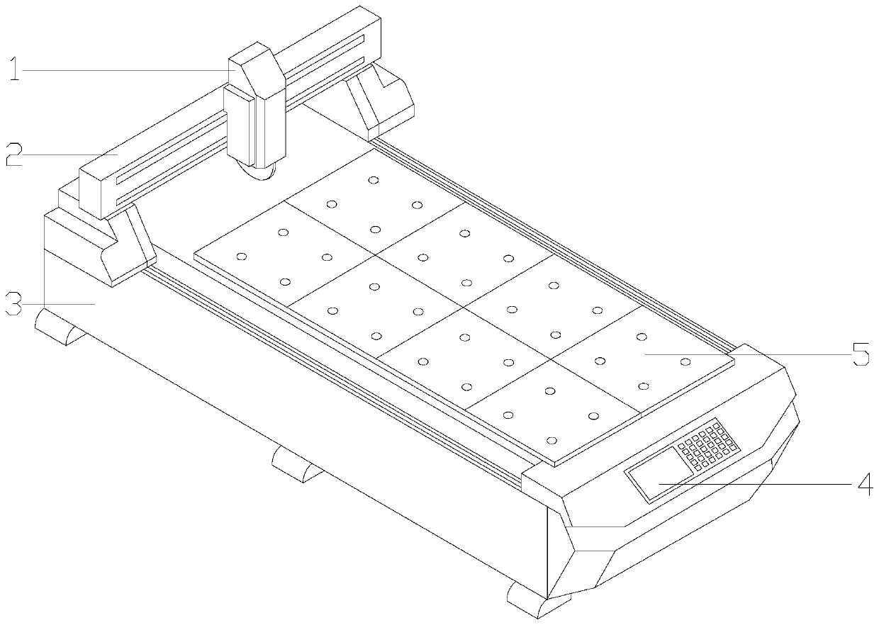
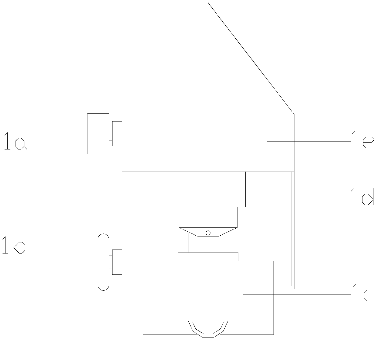
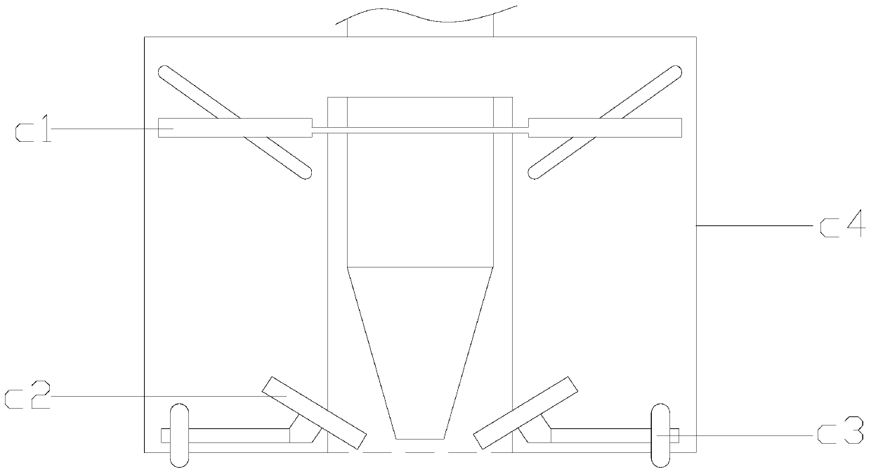
[0023] see Figure 1-Figure 2 , the present invention provides a laser material scoring machine for absorbing and removing debris. 3 is a rectangular structure and is installed horizontally on the ground. The bottom of the sliding adjustment rod 2 is matched with the guide rail on the equipment support platform 3 by using a gap. The intelligent control system 4 is nested on the surface of the equipment support platform 3 and is connected with the equipment support platform 3 are electrically connected, the glass fixing platform 5 is located above the equipment support platform 3 and the bottom surface is attached to the upper surface of the equipment support platform 3, the left side of the scoring tool holder 1 is in clearance fit with the sliding adjustment rod 2, and the scoring tool holder 1 adopts clearance fit. The marking knife holder 1 is composed of a driving roller 1a, a glass scoring knife 1b, a debris remover 1c, a rotation adjustment device 1d, and a knife holder ...


PUM


Abstract

The invention discloses a laser material nicking machine capable of adsorbing and removing scraps. The nicking machine structurally comprises a nicking tool rest, a sliding adjusting rod, an equipmentsupporting table, an intelligent control system and a glass fixing table. The equipment supporting table is horizontally installed on the ground. The sliding adjusting rod is in clearance fit with the equipment supporting table. The intelligent control system is nested on the surface of the equipment supporting table. The laser material nicking machine is provided with a chipping remover. An anti-collision structure promotes a glass cutter to stably get close to laser glass. Glass is prevented from being broken due to too high moving speed. Meanwhile, glass chips are removed thoroughly in a nicking process. Friction generated by the glass chips in the nicking process of the glass cutter is avoided. The glass nicking efficiency is improved, and meanwhile, abrasion of the glass cutter is reduced. The service life of the nicking machine is effectively prolonged.

Description

technical field [0001] The invention relates to laser material processing, in particular to a laser material marking machine for absorbing and removing debris. Background technique [0002] With the rapid development of society, the application range of laser equipment is becoming wider and wider, and laser glass is the main laser material in laser equipment. Before cutting laser glass, it is necessary to use a scoring machine to form scratches on the glass plate. Laser glass is divided and marked, but the current technical considerations are not perfect, and it has the following disadvantages: when the glass knife of the scoring machine is scoring the laser glass, glass debris will remain in the scoring groove. When the required scoring depth is large At the same time, the glass knife needs to roll back and forth to score, which will cause friction between the glass knife and the glass debris in the scoring groove during the back and forth scoring process, which not only re...

Claims


Application Information

Patent Timeline
IPC IPC(8): B23K26/362B23K26/70
CPCB23K26/362B23K26/70B23K26/702
Inventor 方雅晴
Owner 方雅晴
Learn More