Check patentability & draft patents in minutes with Patsnap Eureka AI!

Tool-type pile cap device for high-frequency vibration of steel pipe pile

A technology of high-frequency vibration and steel pipe piles, which is applied in sheet pile walls, foundation structure engineering, construction, etc., can solve the problems of difficult construction safety hazards, increase the use of on-site materials, increase labor input, etc., and reduce on-site construction The effect of time and material investment, ensuring the quality of pile sinking, and improving safety

Inactive Publication Date: 2020-04-24
SHANGHAI FOUND ENG GRP
View PDF4 Cites 0 Cited by
  • Summary
  • Abstract
  • Description
  • Claims
  • Application Information

AI Technical Summary

Problems solved by technology

[0002] At present, the minimum distance between the conventional vibratory hammer clamps is 650mm, which can meet the requirements when laying large-scale steel pipe piles, but in engineering parts that require high demand for small-size steel pipe piles such as ramp construction, conventional clamps cannot be used for pile sinking
The conventional method on site is to weld steel pipe piles that can meet the size of the fixture. This method requires manual climbing and welding. The construction is difficult and will also cause corresponding safety hazards. The effect is not ideal, which prolongs the construction period and increases labor input. It also increases the amount of materials used on site, which significantly increases the construction cost

Method used


Image

  • Tool-type pile cap device for high-frequency vibration of steel pipe pile
  • Tool-type pile cap device for high-frequency vibration of steel pipe pile

Examples


Embodiment Construction

[0013] The embodiments of the present invention will be further described below in conjunction with the accompanying drawings and specific examples.

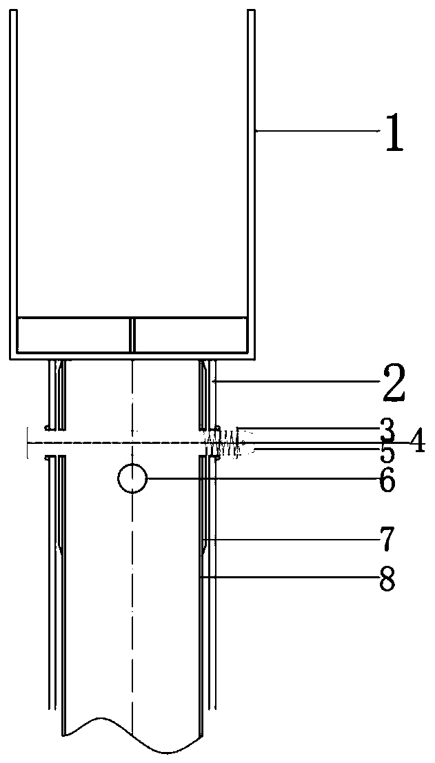
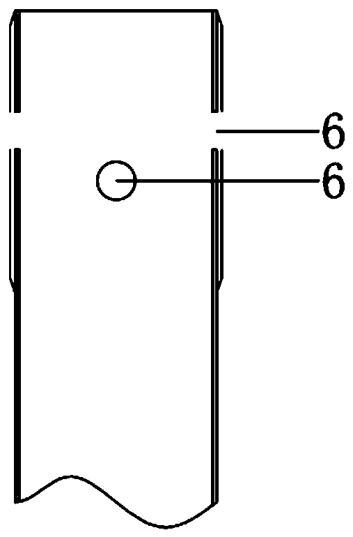
[0014] Such as figure 1 , Shown in 2, the steel pipe pile high-frequency vibration tool type pile cap device of the present invention includes a pile cap and a pin bolt 5 . The pile cap is composed of a pile cap upper part 1, a pile cap lower part 2 and the like. The lower part 2 of the pile cap and the reinforcing ring 7 of the steel pipe pile 8 are closely nested, and the lower part 2 of the pile cap is connected to the two orthogonal holes 6 reserved on the reinforcing ring 7 of the steel pipe pile 8 through the two cross pins 5 . Buckle together, pin bolt 5 heads are close to pile cap lower part 2, and pin bolt 5 afterbody has nut 3 to be tightly fixed on pile cap lower part 2 outer wall by screw thread, and is locked by pin hole 4. Ensure that the steel pipe pile 8 does not generate relative displacement between the pile ...


PUM


Abstract

The invention relates to a tool-type pile cap device for high-frequency vibration of a steel pipe pile. The tool-type pile cap device includes an upper part of a pile cap and a lower part of the pilecap. The lower part of the pile cap sleeves a reinforcing ring of the steel pipe pile closely, the lower part of the pile cap and two orthogonal holes reserved in the reinforcing ring of the steel pipe pile are buckled together through two bolt pins in cross, the heads of bolt pints are closely attached to the lower part of the pile cap, the tail parts of the bolt pins are fastened to the outer wall of the lower part of the pile cap through nuts and are locked by pin holes, and it is ensured that relative displacement is not generated between the pile cap device and the steel pipe pile when the steel pipe pile is hit in a high-frequency vibrating mode by a vibrating hammer. The tool-type pile cap device is easy to operate, the pile cap is closely attached to the steel pipe pile by using the bolt pins, the close reinforcement of the steel pipe pile is realized by using a pin bolt cross pin reinforcement method, and the deformation of the pile cap and of the steel pipe pile at the time of high-frequency pile sinking is reduced; and the pile sinking quality of the steel pipe pile is effectively ensured, while on-site construction time and material input are reduced, and the construction cost is saved.

Description

technical field [0001] The invention is a tool-type pile cap device for high-frequency vibration of steel pipe piles, in particular a pile cap device suitable for the construction of small-diameter steel pipe piles. Background technique [0002] At present, the minimum distance between conventional vibratory hammer clamps is 650mm, which can meet the requirements for embedding large-scale steel pipe piles. However, conventional clamps cannot be used for pile sinking in engineering parts that require high demand for small-size steel pipe piles such as ramp construction. The conventional method on site is to weld steel pipe piles that can meet the size of the fixture. This method requires manual climbing and welding. The construction is difficult and will also cause corresponding safety hazards. The effect is not ideal, which prolongs the construction period and increases labor input. It also increases the usage of on-site materials, which significantly increases the construct...

Claims


Application Information

Patent Timeline
IPC IPC(8): E02D13/10E02D7/18
CPCE02D7/18E02D13/10
Inventor 连海建金仁兴张振华李中言
Owner SHANGHAI FOUND ENG GRP
Features
  • R&D
  • Intellectual Property
  • Life Sciences
  • Materials
  • Tech Scout
  • Unparalleled Data Quality
  • Higher Quality Content
  • 60% Fewer Hallucinations
Learn More