Driving device for optical inspection outside material cabin and exposure platform

A technology of driving device and installation platform, applied in the direction of lifting device, analyzing material, measuring device, etc., can solve the problems that the driving mechanism cannot adapt to the space environment, safety and reliability cannot meet the space station, etc., to achieve all-round monitoring, satisfaction Safety and reliability, the effect of high safety and reliability

Active Publication Date: 2020-04-24
TECH & ENG CENT FOR SPACE UTILIZATION CHINESE ACAD OF SCI
View PDF13 Cites 2 Cited by
  • Summary
  • Abstract
  • Description
  • Claims
  • Application Information

AI Technical Summary

Problems solved by technology

[0025] The technical problem to be solved by the present invention is that there is currently no relevant drive mechanism for optical inspection of materials outside the cabin, and the general drive mechanism cannot adapt to the space environment, and the safety and reliability cannot meet the requirements of the space station.

Method used


Image

  • Driving device for optical inspection outside material cabin and exposure platform
  • Driving device for optical inspection outside material cabin and exposure platform
  • Driving device for optical inspection outside material cabin and exposure platform

Examples


Embodiment 1

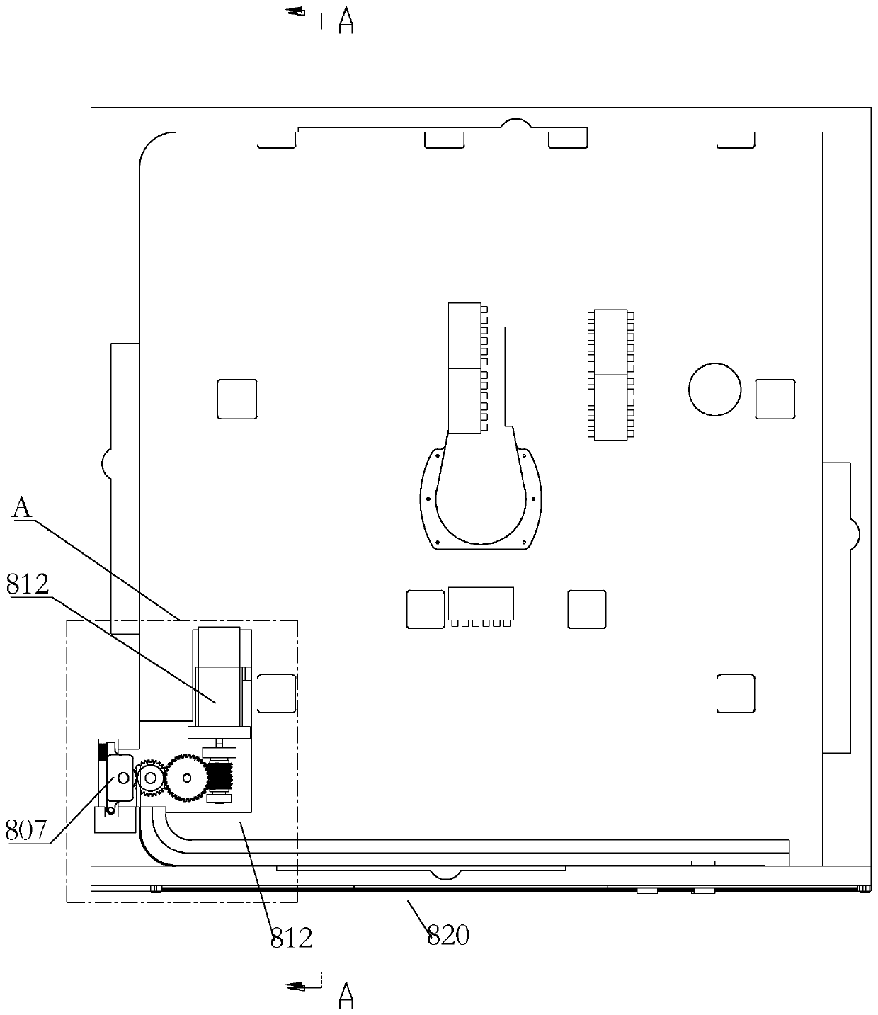
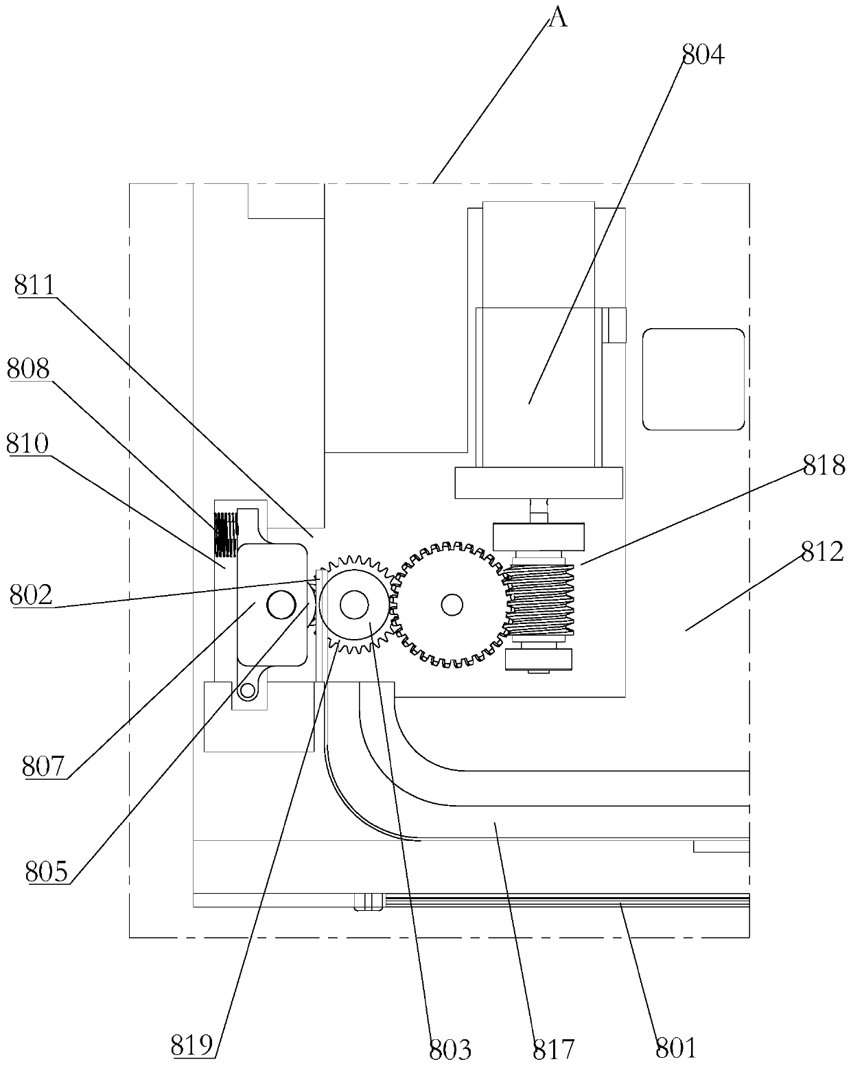
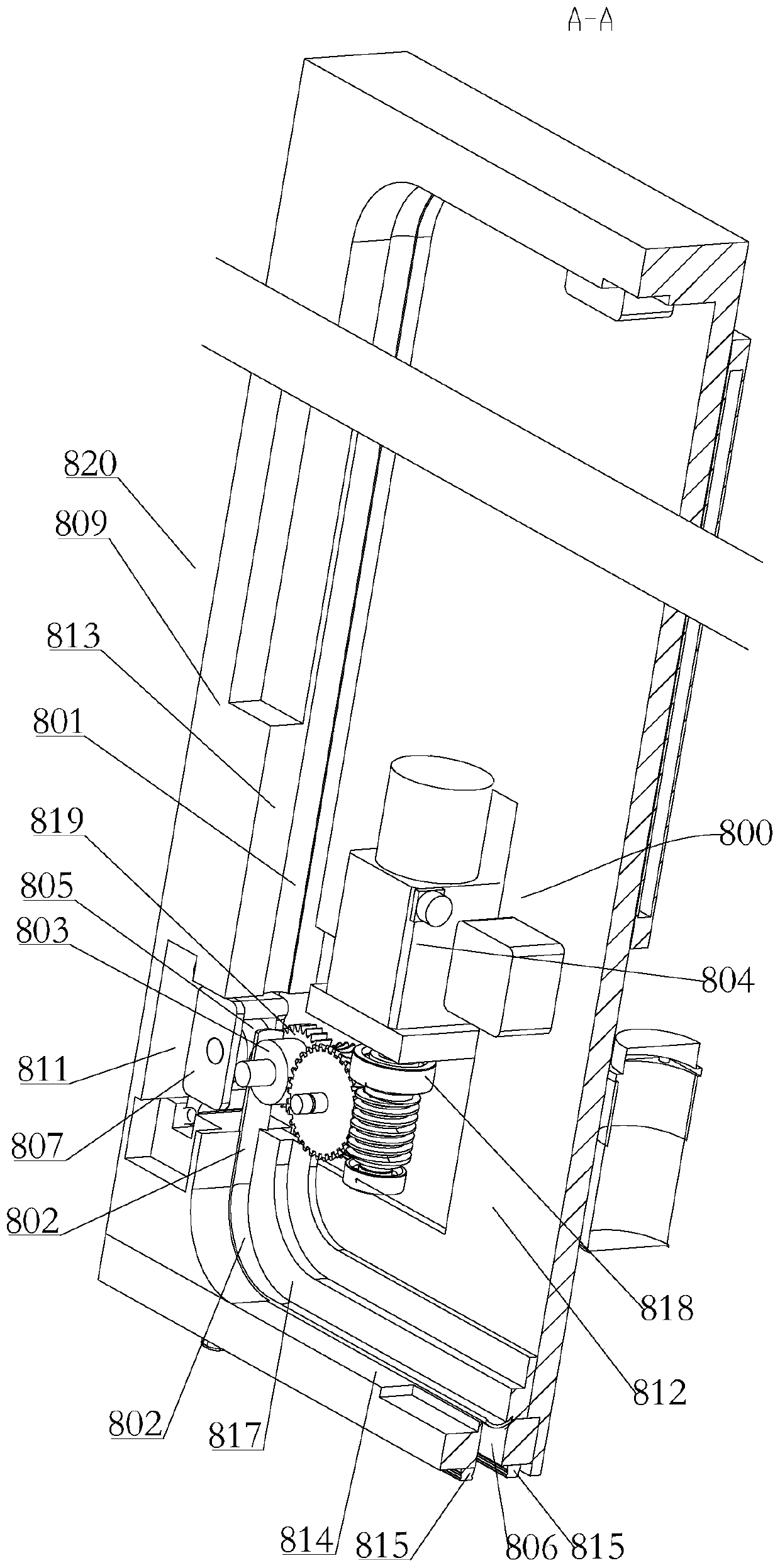
[0078] Such as Figure 1-Figure 9 As shown, a driving device for optical inspection of materials outside the cabin in this embodiment includes:

[0079] The track 801 for the steel belt 802 to move; the steel belt is the transmission actuator, which utilizes the steel belt's own rigidity to drive the steel belt to reciprocate linearly in a limited space under the drive of the steel belt friction wheel;

[0080] The driving friction wheel 803 is connected with the driving mechanism 804 and rotates under the driving of the driving mechanism 804; the driving mechanism 804 can be selected from a driving motor; the driving friction wheel is a steel belt clamping device, which forms a normal direction on the steel belt by clamping Compression force, providing support for friction drive;

[0081] The driving friction wheel 805 is arranged side by side with the driving friction wheel 804 at intervals, and is located on both sides of the track 801 respectively, and the steel belt 802 ...

Embodiment 2

[0115] A material exposed platform outside the cabin of this embodiment, such as Figure 1-Figure 9 As shown, it includes a test box, an optical inspection module, an installation platform 820 and the drive device described in Embodiment 1, the test box is installed on the installation platform 820, and the exposed surface of the test box after opening faces the installation The surroundings of the platform 820 are arranged, and the track 801 is arranged at a position close to the peripheral side of the installation platform 820; the bottom of the bracket 701 is provided with a connecting plate 714 arranged vertically, and the connecting plate 714 passes through the slot 806 Connected with the steel belt 802, the optical inspection module 1 reciprocates in a direction perpendicular to the installation platform 820 under the drive of the steel wire rope 705, and surrounds the installation platform 820 under the drive of the steel belt 802 The peripheral side of the machine reci...


PUM


Abstract

The invention relates to a driving device for optical inspection outside a material cabin and an exposure platform. The driving device comprises a track for moving and walking of a steel belt, a driving friction wheel, a transmission friction wheel, a support, a steel wire rope and a bearing plate, wherein the steel belt is clamped between the driving friction wheel and the transmission friction wheel; a guide rail I perpendicular to the steel belt is installed on one side of the support, a driving mechanism is installed at the bottom of one side of the support, the driving end of the drivingmechanism is connected with a driving steel wire rope winding wheel, a steel wire rope idle wheel is installed at the top of one side of the support, and a steel wire rope tightening device is installed on the other side of the support; one end of the steel wire rope is connected to the driving steel wire rope winding wheel, and the other end is wound on the steel wire rope idle wheel and then connected to the steel wire rope tightening device; the bearing plate is used for mounting an optical inspection module, is installed on the guide rail I in a sliding manner and is connected to the steelwire rope. According to the invention, X-direction movement is achieved through steel belt driving, Y-axis movement is achieved through steel wire rope driving, and the driving requirement of the optical inspection module under the special space environment effect can be met.

Description

technical field [0001] The invention relates to the related field of aerospace material exposure, in particular to a driving device and an exposure platform for optical inspection of materials outside the cabin. Background technique [0002] In space science research, it is inseparable from the use of various materials, especially new materials. The purpose of material space environment exposure experiment is to study the service behavior of materials under the effect of special space environment. [0003] Therefore, in the material cabin exposure experiment, how to realize a material cabin that can provide conditions for the on-orbit exposure of materials, provide conditions for the on-orbit movement of the optical imaging inspection module, and realize on-orbit detection in a special and complex space The external exposure platform is an important problem that needs to be solved urgently. [0004] Moreover, the movement mechanism applied to the space environment, compare...

Claims


Application Information

Patent Timeline
Patent Type & Authority Applications(China)
IPC IPC(8): G01N21/84G01N21/01B66F7/02B64G1/66B64G1/10
CPCG01N21/84G01N21/01B66F7/02B64G1/105B64G1/66
Inventor 张聚乐张伟贵王乐天王珂康博奇王辅辅冯振华
Owner TECH & ENG CENT FOR SPACE UTILIZATION CHINESE ACAD OF SCI
Why Eureka
Try Eureka