Suspension potential elimination circuit

A technology to eliminate circuits and floating potentials, applied to electrical components, output power conversion devices, etc., to achieve the effects of improving safety and reliability, reducing size and capacity, and easy production process

Pending Publication Date: 2020-04-24
XIAN XJ POWER ELECTRONICS TECH +5
View PDF5 Cites 2 Cited by
  • Summary
  • Abstract
  • Description
  • Claims
  • Application Information

AI Technical Summary

Problems solved by technology

[0006] The purpose of the present invention is to provide a floating potential elimination circuit for solving the problem of floating potential in the existing DC transformer

Method used


Image

  • Suspension potential elimination circuit
  • Suspension potential elimination circuit
  • Suspension potential elimination circuit

Examples


Embodiment 1

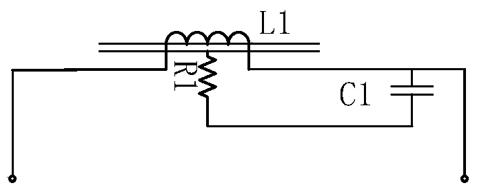
[0028] This embodiment proposes a floating potential elimination circuit, such as figure 2 As shown, it includes a first winding L1 with an iron core, a first capacitor C1 and a first resistor R1, wherein the first winding L1 is wound on the iron core and is used to connect the output end of the DC / DC module in the DC transformer; One end of a capacitor C1 is connected to the first winding L1, the other end of the first capacitor C1 is connected to the first resistor R1, and the first resistor R1 is connected to the iron core of the first winding L1.

[0029] The floating potential elimination circuit can make the iron core of the inductor (winding) electrically connected to the output side of the circuit, effectively reduce the floating potential of the iron core in the DC transformer, avoid the partial discharge phenomenon of the DC transformer, and improve the safety and reliability of the DC transformer. reliability.

[0030] The floating potential elimination circuit of...

Embodiment 2

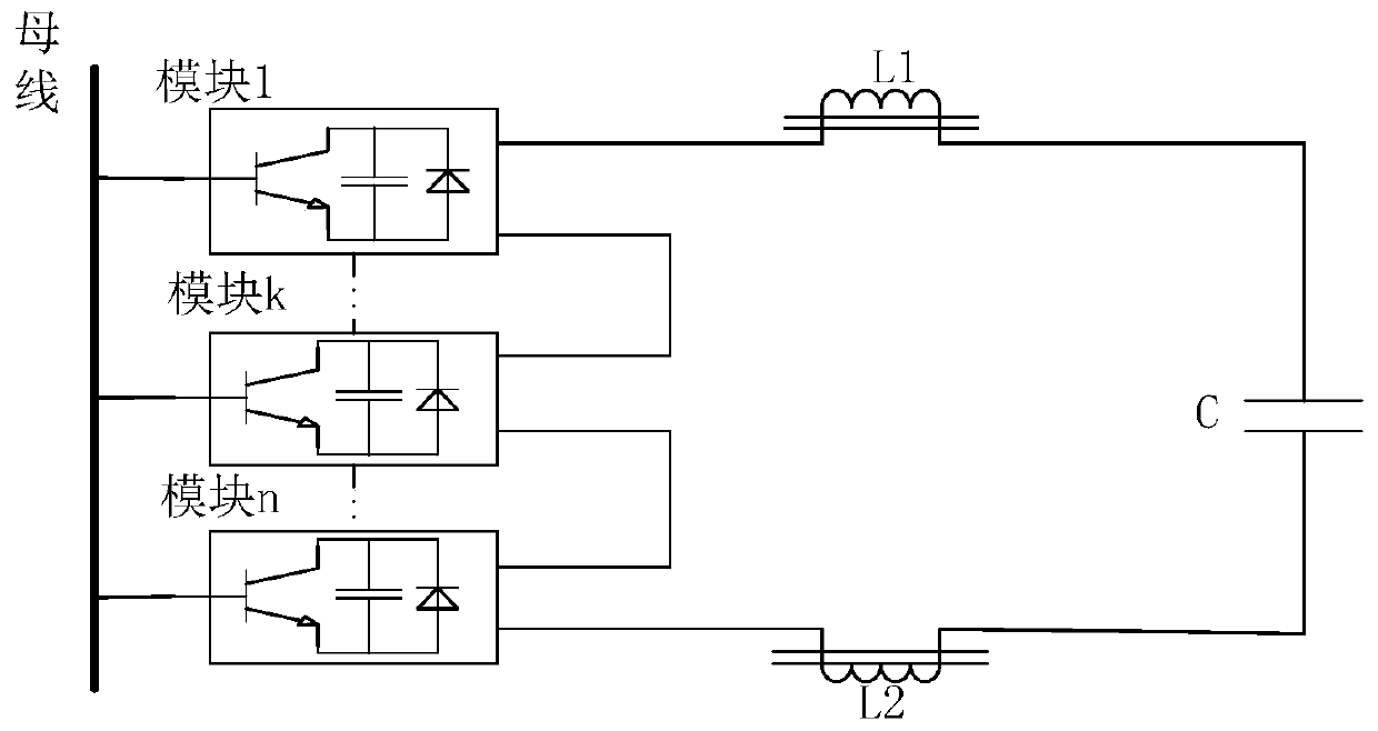
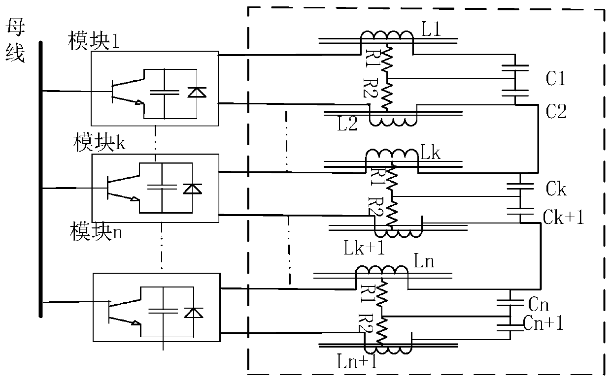
[0033] like image 3 The shown DC transformer includes at least n DC / DC modules, which are respectively module 1, ..., module k, ..., module n, and the output terminals of each DC / DC module are connected with floating potential elimination sub-circuits with the same structure , all the floating potential elimination sub-circuits constitute the floating potential elimination circuit proposed in this embodiment, see image 3 The part inside the dotted box.

[0034] The following takes the floating potential elimination sub-circuit of module 1 as an example. The floating potential elimination sub-circuit includes: a positive inductor L1 with an iron core, a negative inductor L2 with an iron core, and a capacitor module.

[0035] The capacitor module includes a positive capacitor C1 and a negative capacitor C2. The positive capacitor C1 and the negative capacitor C2 are connected in series. At the same time, the series point of the positive capacitor C1 and the negative capacito...


PUM


Abstract

The invention relates to a suspension potential elimination circuit, which belongs to the technical field of direct current distribution networks. The circuit comprises a first winding with an iron core and an output end used for being connected with a DC/DC module in a direct current transformer, and a first capacitor. One end of the first capacitor is connected with the first winding, and the other end of the first capacitor is connected with a first resistor. The first resistor is connected with an iron core of the first winding. According to the suspension potential elimination circuit, the resistor is connected with the iron core of the first winding, and the resistor is connected with the capacitor, so that the iron core of the winding is electrically connected with the output side of the circuit; the suspension potential of the iron core in the direct current transformer is effectively reduced; the partial discharge phenomenon of the direct current transformer is avoided; and the safety and reliability of the direct current transformer are improved. The suspension potential elimination circuit is suitable for direct current transformers of various structures, such as directcurrent transformers of distributed cascaded topological structures, and can also be applied to power-frequency direct current transformers and high-frequency direct current transformers.

Description

technical field [0001] The invention relates to a floating potential elimination circuit, which belongs to the technical field of DC distribution network. Background technique [0002] With the increase of DC distribution network projects and the rapid development of DC distribution network technology, DC equipment (such as DC transformers) have been more widely used in actual DC transmission projects. Larger features, the increase in the number of DC power distribution equipment modules required and the increase in equipment volume, how to better access distributed power sources and DC loads has become a more serious problem, so it is urgently needed to be smaller in size and more integrated High DC equipment to improve system security and operating efficiency. [0003] In the prior art, the DC transformer adopts DC / DC modules connected in series to connect inductances L1 and L2 with iron cores in a unified way, and output them to the capacitor C. like figure 1 As shown,...

Claims


Application Information

Patent Timeline
Patent Type & Authority Applications(China)
IPC IPC(8): H02M1/32
CPCH02M1/32
Inventor 刘增哲安昱柳龙杨欣然张帆石松盛万兴李蕊吴鸣孙丽敬李彬彬聂明珍
Owner XIAN XJ POWER ELECTRONICS TECH
Why Eureka
Try Eureka