Transcatheter valve replacement system

A valve replacement and catheter technology, applied in the field of medical devices, can solve problems such as difficulty, poor affixation, and large diameter of the delivery catheter, and achieve the effects of lower position requirements, prevention of paravalvular leakage, and low loading difficulty

Active Publication Date: 2020-04-28
NINGBO JENSCARE BIOTECHNOLOGY CO LTD
View PDF15 Cites 8 Cited by
  • Summary
  • Abstract
  • Description
  • Claims
  • Application Information

AI Technical Summary

Problems solved by technology

In this solution, the detachable connection operation between the anchor release device and the fixing unit is relatively complicated, requires high precision, and is difficult to pre-install, and after the sheath is withdrawn, the stress on the detachable connection is large, which is easy to damage the implanted device and anchor release device; before anchoring, the bending of the delivery tube needs to rely on the support structure to fix the corner, otherwise the distal end of the delivery tube is difficult to stick to the fixing unit, and, in the process of sheath retraction and sheath release Because the length of the delivery tube changes, before anchoring, there may be a gap between the distal end of the delivery tube and the fixation unit, which is not firmly attached, which affects the anchoring effect, and the surgical risk is high; for implanted devices that require multi-point fixation , this solution needs to be equipped with multiple delivery tubes at the same time, the structure is complex, and the diameter of the delivery tube is large; after the anchoring operation is completed, re-anchoring cannot be performed, and the operation risk is high

Method used


Image

  • Transcatheter valve replacement system
  • Transcatheter valve replacement system
  • Transcatheter valve replacement system

Examples


Embodiment Construction

[0042] In order to make the object, technical solution and advantages of the present invention clearer, the present invention will be further described in detail below with reference to the accompanying drawings and examples.

[0043] The proximal end in the present invention refers to the end close to the control handle or the operator, and the distal end refers to the end away from the control handle or the operator.

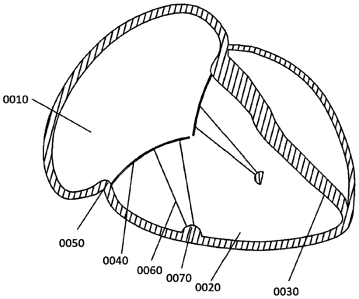
[0044] This embodiment takes transcatheter tricuspid valve replacement valve as an example, as Figure 1a as shown, Figure 1a Major anatomy of the right heart is shown, including the right atrium 0010, right ventricle 0020, interventricular septum 0030, native valve leaflets 0040, tricuspid annulus 0050, chordae tendineae 0060, and papillary muscles 0070, heavily closed in the tricuspid valve In insufficiency, the tricuspid annulus 0050 will be significantly enlarged in most patients. The valve replacement prosthesis of the present invention is implanted into...


PUM


Abstract

The present application relates to a transcatheter valve replacement system. The system includes a valve replacement prosthesis, a delivery catheter, a control handle and an anchoring device; the valve replacement prosthesis includes a valve stent, an artificial valve leaflet and an adaptive covered stent, the artificial valve leaflet is arranged in the valve stent, the adaptive covered stent is connected to the outer periphery of the valve stent, the valve replacement prosthesis is provided with an anchored unit, and the anchored unit is fixed to heart tissue by the anchoring device; and theanchoring device is arranged in the delivery catheter, the anchoring device includes an anchoring needle, an anchoring needle catheter, an anchoring needle push rod, and a controllable guiding device,the anchoring needle is pre-installed in the distal end of the anchoring needle catheter, the distal end part of the anchoring needle catheter has a flexible structure, one end of the controllable guiding device is detachably connected to the anchored unit, and the controllable guiding device can control the distal end part of the anchoring needle catheter to form a fixed bend angle in the radialdirection and make the distal end of the anchoring needle catheter adhered to the anchored unit.

Description

technical field [0001] The invention relates to a medical device, in particular to a transcatheter valve replacement system. Background technique [0002] Minimally invasive transcatheter treatment of cardiovascular diseases has gradually become the main treatment method, such as coronary stents, heart valves, occluders, great vessel stents and other cardiovascular implanted devices, which need to be delivered to the human body through delivery devices The expected ideal position, and the implanted device needs to be fixed after reaching the target position, and the fixation of the heart valve prosthesis is particularly important. In the prior art, the fixation of the aortic valve and the pulmonary valve mainly depends on the radial support force of the valve support, and the clamping parts or protrusions, depressions, etc. are set on the valve support and fixed by using the shape and characteristics of the anatomical structure; the mitral valve The fixation of valves and...

Claims


Application Information

Patent Timeline
Patent Type & Authority Applications(China)
IPC IPC(8): A61F2/24
CPCA61F2/2412A61F2/2418A61F2/2463A61F2/2466
Inventor 吕世文陈志徐进
Owner NINGBO JENSCARE BIOTECHNOLOGY CO LTD
Why Eureka
Try Eureka