A Vibration Isolator with Negative Stiffness Balance Position Adjustment Function
A technology of balanced position and negative stiffness, applied in the direction of spring/shock absorber, vibration suppression adjustment, non-rotation vibration suppression, etc. Effect
- Summary
- Abstract
- Description
- Claims
- Application Information
AI Technical Summary
Problems solved by technology
Method used
Image
Examples
Embodiment 1
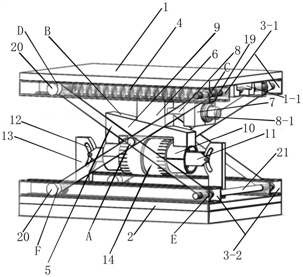
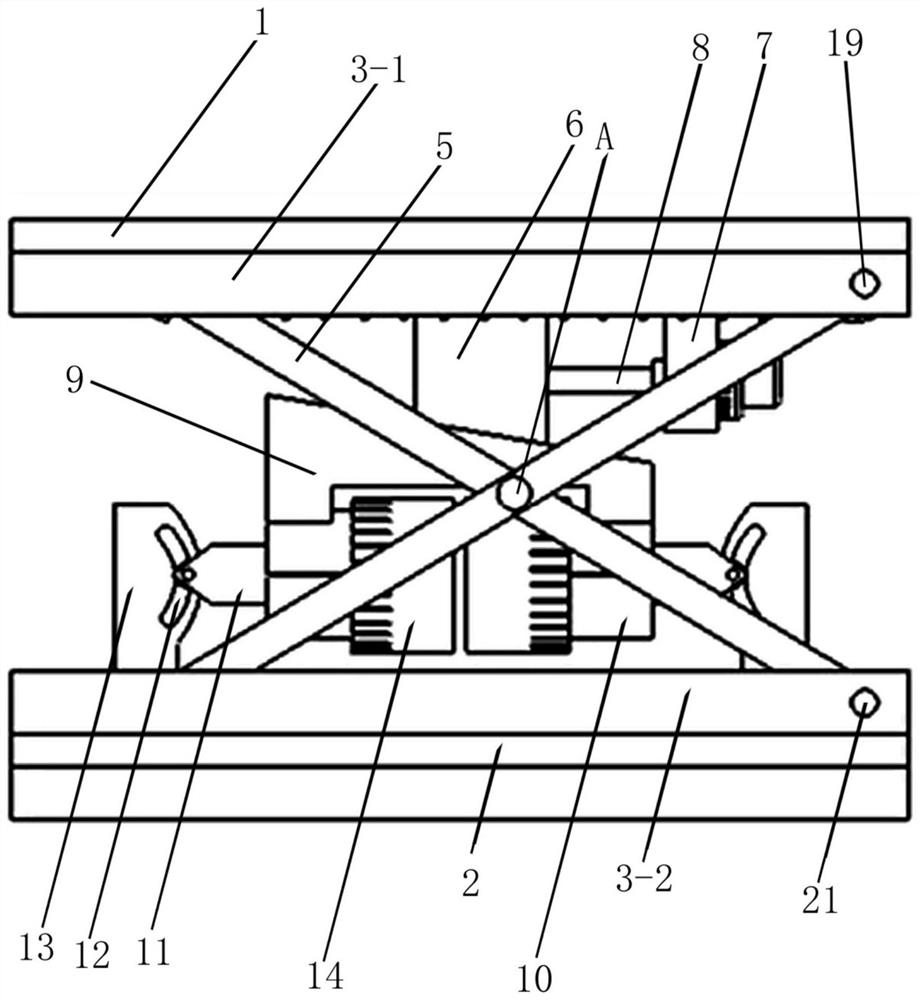
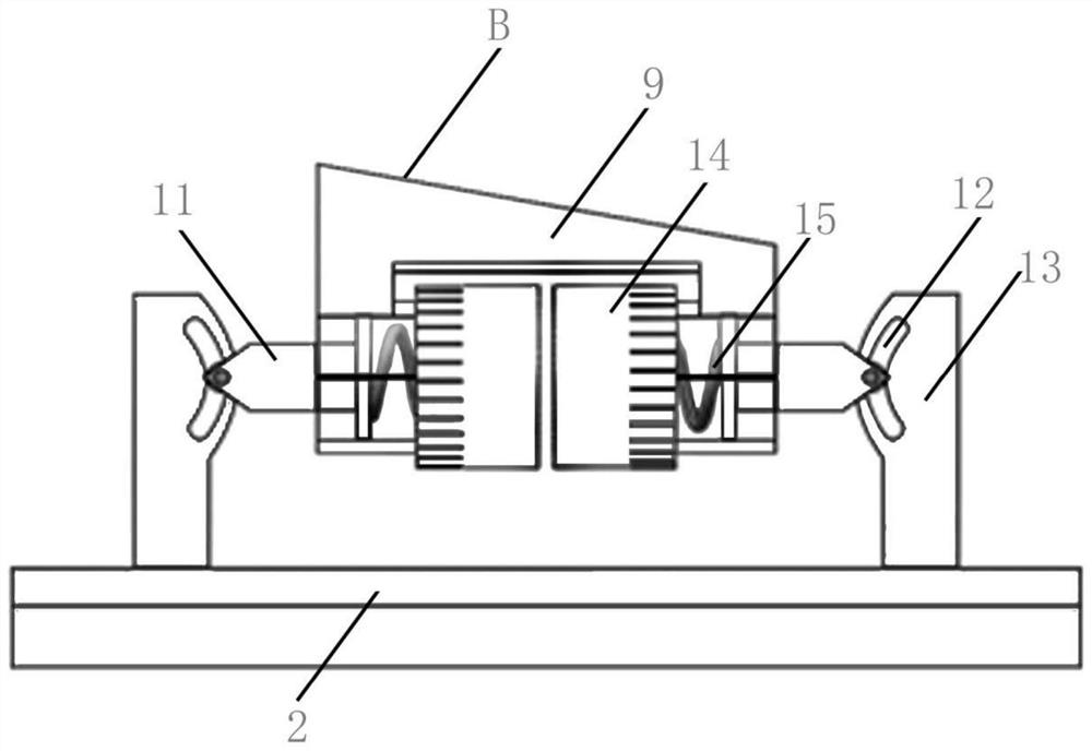
[0081] The adjustment mechanism includes a T-shaped block (6) with a sloped bottom surface, a scale block (7) and an adjustment bolt (8). The adjustment bolt (8) passes through the scale block (7) and is connected with the T-shaped block (6). An adjusting nut (8-1) is arranged on the bolt, and the adjusting nut (8-1) is threadedly matched with the adjusting bolt (8), and the axial relative position between the adjusting nut (8-1) and the scale block (7) remains unchanged; (that is, the adjustment nut (8-1) can only rotate, but the (axial) displacement between the scale block (7) remains relatively unchanged, that is, the adjustment nut (8-1) does not move axially, so that the rotation Control the axial movement of the adjusting bolt to control the movement of the T-shaped block (6), while the adjustment nut (8-1) can only rotate and the axial displacement remains unchanged. Set a ring of bosses on the outer edge of the four sides, and then use the 7-shaped key to lock it, as s...
Embodiment 2
[0141] like Figure 29-33 :
[0142] The adjusting mechanism comprises a vertical adjusting nut (17) connected to the bottom of the upper top plate (1) (with scale) and an adjusting rod (18) connected to the top of the upper bearing block (9), the upper end of the adjusting rod (18) Cooperate with the vertical adjustment nut (17), and control the lifting of the adjustment rod (18) by the screwing of the vertical adjustment nut (17). (Adjusting nut (17) can rotate, but axially fixed, prior art, its principle can adopt the principle of aforementioned adjusting nut (8-1))
[0143] When the track (12) was an oblique bar shape, a "eight" shape was formed between the two tracks (12) (as Figure 29 , 30 , Shown in 32,33, is exactly that the upper end is inwardly inclined).
[0144] In the structures of the above two embodiments:
[0145] One of the upper end points (C) of the scissor support rod (5) is movably connected with the connecting rod shaft (19) (passing through the sli...
PUM
 Abstract
Description
Claims
Application Information
 - R&D
- Intellectual Property
- Life Sciences
- Materials
- Tech Scout
- Unparalleled Data Quality
- Higher Quality Content
- 60% Fewer Hallucinations
Browse by: Latest US Patents, China's latest patents, Technical Efficacy Thesaurus, Application Domain, Technology Topic, Popular Technical Reports.
© 2025 PatSnap. All rights reserved.Legal|Privacy policy|Modern Slavery Act Transparency Statement|Sitemap|About US| Contact US: help@patsnap.com


