Control method for converter and driving controller

A converter control and drive controller technology, applied to control/regulation systems, DC power input conversion to DC power output, instruments, etc., can solve the problem that the chip is out of control, cannot work immediately, cannot be woken up, even if the fault signal is cancelled. , and only wait until the chip rests before automatically waking up and other issues to achieve the effect of protecting damage

Pending Publication Date: 2020-04-28
苏州源特半导体科技有限公司
View PDF5 Cites 6 Cited by
  • Summary
  • Abstract
  • Description
  • Claims
  • Application Information

AI Technical Summary

Problems solved by technology

Although the structure of this circuit is simple and practical, it has obvious defects: poor self-protection ability
The base drive current of the triode gradually increases with the increase of the load, which causes the triode to enter an overdrive state and the current of the switch collector reaches a peak value, and the device is easily damaged during the switching process.
Although this control method can protect the chip from damage, it also has obvious disadvantages, that is, once it enters the protected sleep state, the chip cannot be woken up. Even if the fault signal is cancelled, it will only wake up automatically after the chip has finished resting. It is equivalent to that the chip is out of control in the sleep state, and the push-pull switching converter cannot immediately work to supply power to the load after the fault signal is cancelled, which is not allowed in some system applications

Method used


Image

  • Control method for converter and driving controller
  • Control method for converter and driving controller
  • Control method for converter and driving controller

Examples


Embodiment Construction

[0028] The following description and drawings illustrate specific embodiments of the invention sufficiently to enable those skilled in the art to practice them. Other embodiments may incorporate structural, logical, electrical, process, and other changes. The examples merely represent possible variations. Individual components and functions are optional unless explicitly required, and the order of operations may vary. Portions and features of some embodiments may be included in or substituted for those of other embodiments. The scope of embodiments of the present invention includes the full scope of the claims, and all available equivalents of the claims.

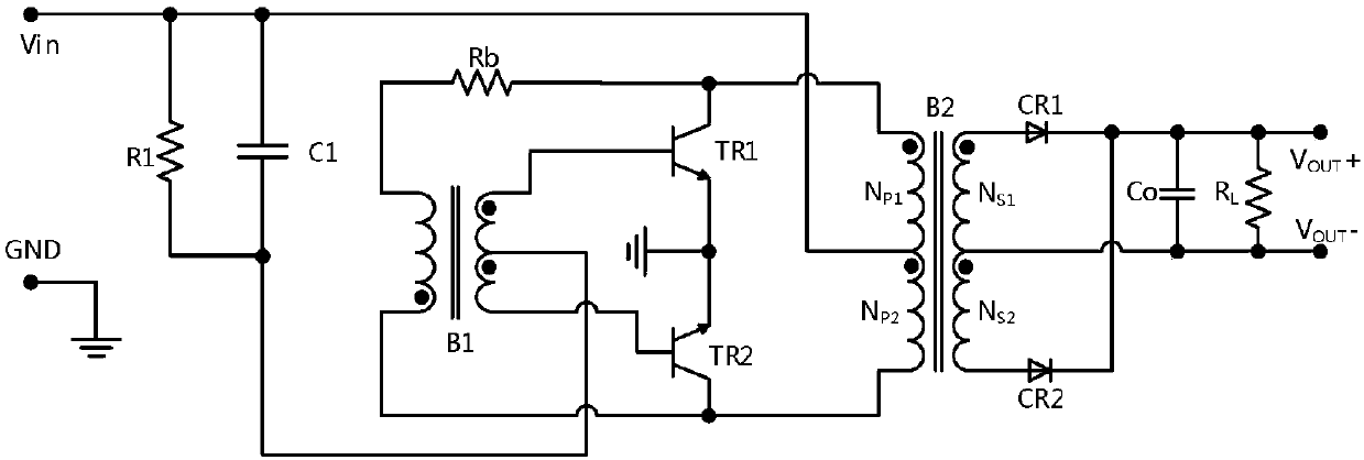
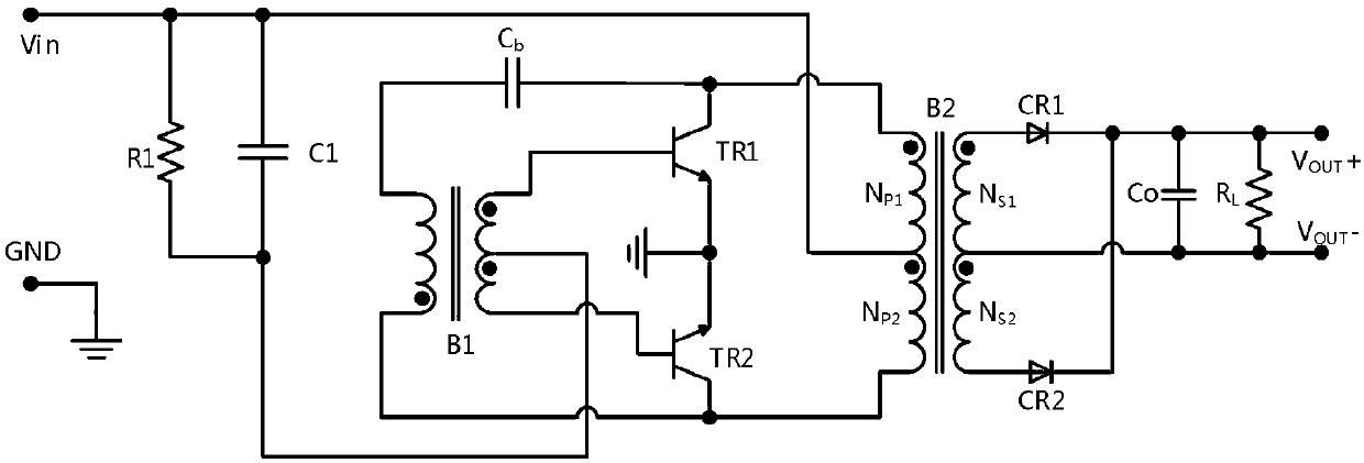
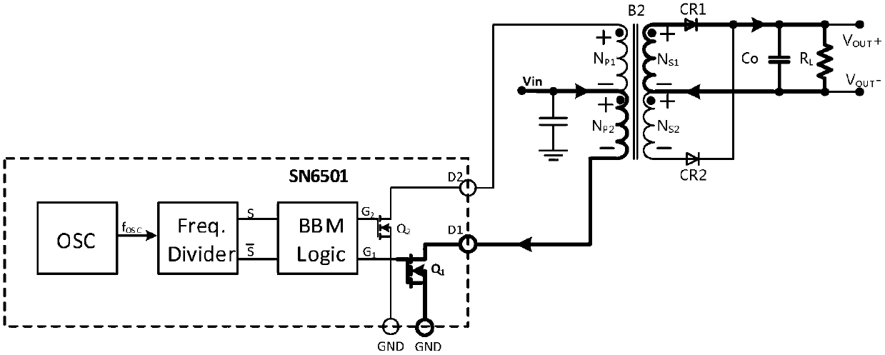
[0029] Such as image 3 As shown, the push-pull controller SN6501, the oscillator OSC generates two complementary logic signals S and Then the BBM Logic module generates two complementary signals G with a certain dead time 2 and G 1 . The complementary driving signal is generated by frequency division, so the width o...


PUM


Abstract

The invention provides a control method for a converter and a driving controller. The power tube of the converter is in three different working states under different detection conditions, namely, a hard switching state, a soft switching state and a stop switching state. A high-reliability over-current and short-circuit protection mode is provided. According to the control method for the converterand the driving controller invention, the advantage of symmetry required by the topological structure of the converter given by an integrated circuit can be obtained; high reliability of the converter is realized through reasonable design; the converter can be recovered after a fault signal is cancelled, and the risk of abnormal power supply of a client due to the fact that the converter cannot be awakened in time in the false dead state of protection is avoided; and not only is possible damage to the power source converter caused by an abnormal state comprehensively and effectively prevented, but also required energy is supplied to a load end to the greatest extent, and thus, the essential tasks of the power source converter are finished.

Description

technical field [0001] The invention belongs to the technical field of switching power converters, and in particular relates to a converter control method and a drive controller. Background technique [0002] Such as figure 1 As shown, the self-excited push-pull converter in the prior art is widely used in micro-power module DCDC isolation converters because of its simple structure, high flux utilization rate and small size. Although the structure of this circuit is simple and practical, it has obvious defects: poor self-protection ability. The base drive current of the triode gradually increases with the increase of the load, which causes the triode to enter an overdrive state and cause the switch collector current to reach a peak value, and the device is easily damaged during the switching process. It is also easily damaged due to overheating when the current or output is short-circuited. [0003] In order to solve the above technical problems, the patent with the publi...

Claims


Application Information

Patent Timeline
Patent Type & Authority Applications(China)
IPC IPC(8): H02M3/337H02M1/32
CPCH02M3/337H02M1/32H02M1/327Y02B70/10
Inventor 崔能伟
Owner 苏州源特半导体科技有限公司
Why Eureka
Try Eureka