Stirring device for ferrite soft magnetic core production

A stirring device and soft magnetic core technology, which is applied to mixers with rotating stirring devices, transportation, packaging, dissolution, etc., can solve the problems of low efficiency and manpower consumption, and achieve labor-saving lifting, efficiency improvement, and meet the needs of use Effect

Inactive Publication Date: 2020-05-01
天长市联嘉磁电科技有限公司
View PDF8 Cites 2 Cited by
  • Summary
  • Abstract
  • Description
  • Claims
  • Application Information

AI Technical Summary

Problems solved by technology

[0004] The purpose of the present invention is to solve the problems of labor-intensive and low efficiency in the prior art, and propose a stirring device for ferrite soft magnetic core production

Method used


Image

  • Stirring device for ferrite soft magnetic core production
  • Stirring device for ferrite soft magnetic core production
  • Stirring device for ferrite soft magnetic core production

Examples


Embodiment 1

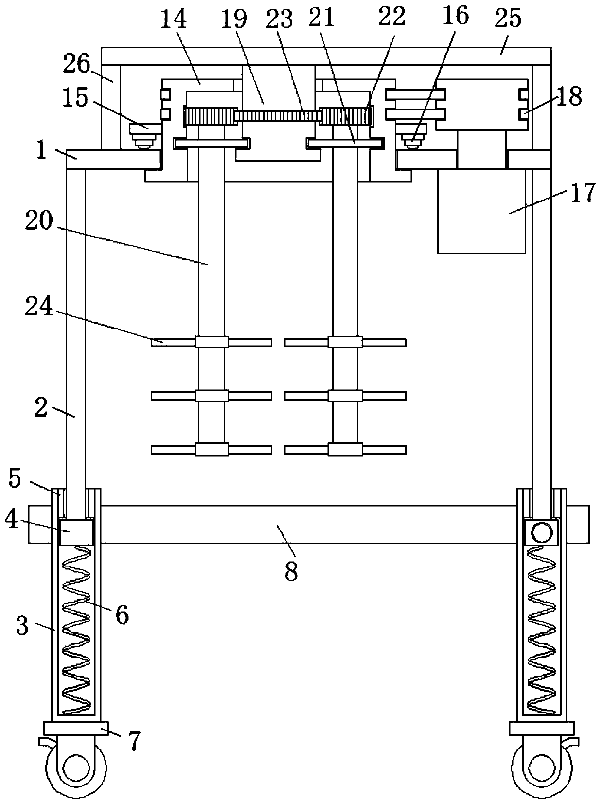
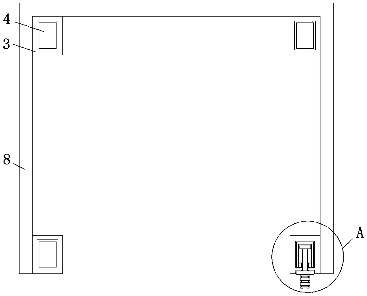
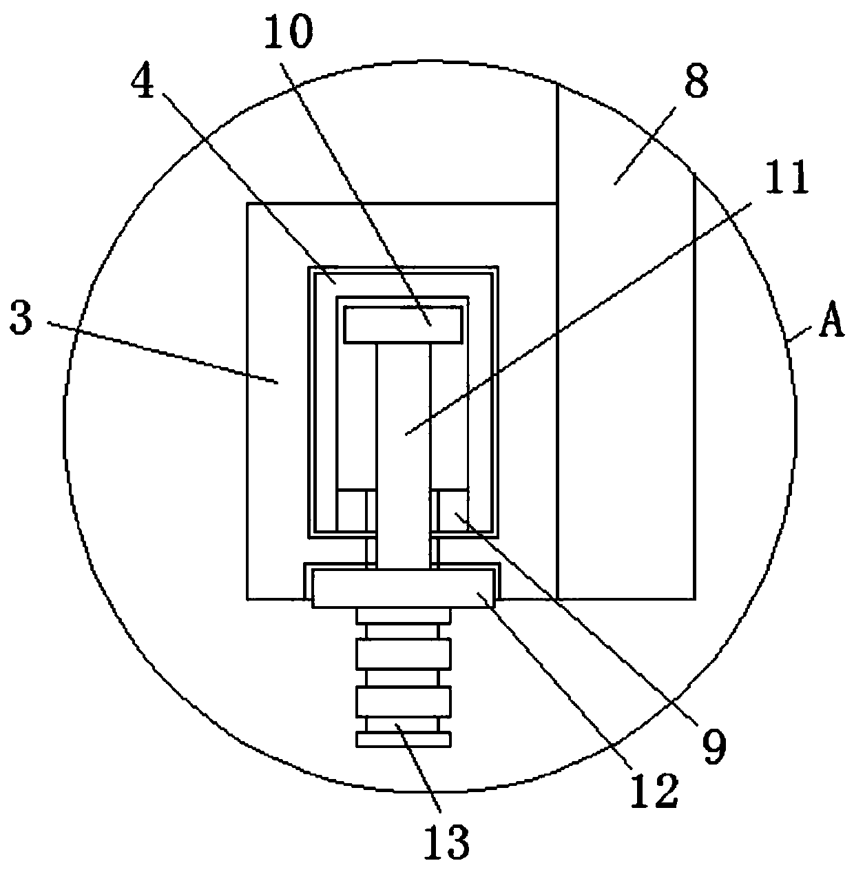
[0024] refer to Figure 1-6 , a stirring device for ferrite soft magnetic core production, comprising a mounting table 1, the four corners of the bottom of the mounting table 1 are fixedly connected with legs 2, the sliding sleeve at the bottom of the leg 2 is provided with a sliding sleeve 3, and the top of the sliding sleeve 3 A top chute is provided, the inner wall of the top opening of the top chute is fixedly connected with the limit ring 15, and the sliding column 4 is slidably connected in the top chute, and the bottom side of the sliding column 4 is arranged between the bottom side inner wall of the top chute. Auxiliary support spring 6 is arranged, and one side of the vertical side of the top chute of the top chute is provided with a slide hole, and one side of the sliding column 4 in the top chute is provided with a side groove, and the opening inner wall of the side groove is fixed Connect the limiting ring 2 9, the slide block 10 is connected horizontally in the si...

Embodiment 2

[0028] Such as Figure 1-6 As shown, this embodiment is basically the same as Embodiment 1. Preferably, the planetary gear 22 is located on the top side of the limiting swivel 21 .

[0029] In this embodiment, both sides of the planetary gear 22 mesh with the sun gear ring 23 and the tooth groove respectively to form a rotation, and the ring groove 1 and the ring groove 2 support the limit swivel 21 in the vertical direction.

Embodiment 3

[0031] Such as Figure 1-6 As shown, this embodiment is basically the same as Embodiment 1. Preferably, locking universal wheels 7 are installed at the bottom ends of the sliding sleeves 3 .

[0032] In this embodiment, the movement of the equipment is facilitated, and the mobility of the equipment is increased.


PUM


Abstract

The invention discloses a stirring device for ferrite soft magnetic core production. The stirring device comprises a mounting table, and supporting legs are fixedly connected to the four corners of the bottom of the mounting table correspondingly. The bottom ends of the supporting legs are sleeved with sliding sleeves in a sliding mode. A top chute is formed in the top of the sliding sleeve. A first limiting ring is fixedly connected to the inner wall of the top opening of the top chute. A sliding column is slidably connected into the top chute. An auxiliary supporting spring is arranged between the bottom side of the sliding column and the inner wall of the bottom side of the top chute, a sliding hole is formed in the vertical side of the top chute of one top chute, a side groove is formed in the side, in the top chute, of the sliding column, and a second limiting ring is fixedly connected to the inner wall of the opening of the side groove. By means of the stirring device for ferritesoft magnetic core production, the material stirring efficiency in the ferrite soft magnetic core production process is greatly improved, lifting of the stirring device is more labor-saving, manpoweris saved, the production efficiency is improved, and the use requirements of people in production and life are met.

Description

technical field [0001] The invention relates to the technical field of ferrite soft magnetic core processing equipment, in particular to a stirring device for ferrite soft magnetic core production. Background technique [0002] Ferrite cores are mainly composed of three metal elements: iron (Fe), manganese (Mn), and zinc (Zn), and are usually called manganese-zinc ferrite. Since the annular ferrite core has no air gap and has the same cross-sectional area, the magnetic effect is very high. The ferrite core has a lot of specifications and sizes, which can be selected according to the material of the magnetic ring, and different The coating simplifies winding and increases breakdown voltage. [0003] During the processing of the existing ferrite soft magnetic core, various raw material powders need to be mixed in the mixing tank. In the process of mixing, single-layer stirring paddles or multi-layer stirring paddles are used. The paddle is installed on the outside of a singl...

Claims


Application Information

Patent Timeline
IPC IPC(8): B01F7/30B01F7/00
CPCB01F27/806B01F27/191B01F27/95
Inventor 吴建芳余建达胡明途
Owner 天长市联嘉磁电科技有限公司
Why Eureka
Try Eureka