Electronic hydraulic brake boosting system

A hydraulic braking and power assist system technology, applied in the direction of brakes, brake transmissions, transportation and packaging, etc., can solve the problems of brake fluid volume loss, high brake fluid pressure, system damage, etc., and achieve safe braking function , multiple functions, and the effect of solving the loss of brake fluid volume

Inactive Publication Date: 2020-05-01
TIANJIN TRINOVA AUTOMOTIVE TECH CO LTD
View PDF6 Cites 4 Cited by
  • Summary
  • Abstract
  • Description
  • Claims
  • Application Information

AI Technical Summary

Problems solved by technology

[0005] Aiming at the deficiencies of the prior art, the present invention provides an electronic hydraulic brake booster system, which solves the problem of brake fluid volume loss in the ABS mode of the electronic hydraulic booster brake system and the problem of excessive brake fluid pressure during the adjustment process. System Corruption Issues

Method used


Image

  • Electronic hydraulic brake boosting system

Examples


Embodiment 1

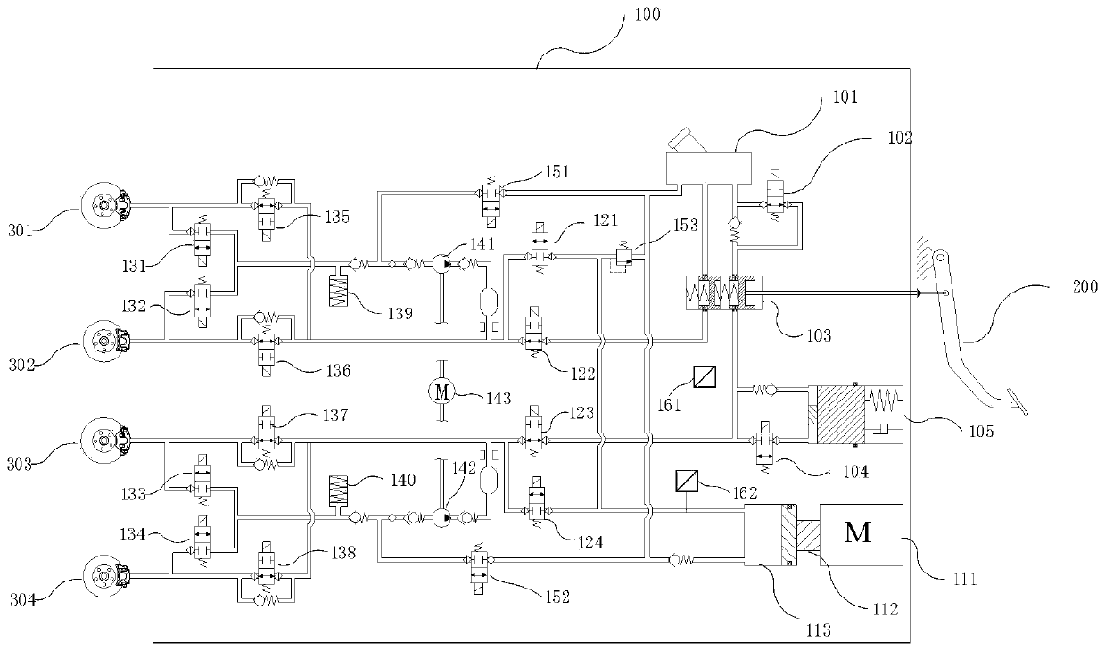
[0024] Such as figure 1 As shown, the embodiment of the present invention provides an electronic hydraulic brake booster system, including an electronic hydraulic brake booster system, a brake pedal, brake wheel cylinder 1, brake wheel cylinder 2, brake wheel cylinder 3 and brake wheel Cylinder four, the electronic hydraulic brake booster system includes a liquid storage tank and a brushless motor, and the liquid storage tank is fixedly connected with the source master cylinder, valve fourteen, valve fifteen and valve sixteen, and the liquid storage tank A master cylinder inlet valve is fixedly connected with one of the source master cylinders, one of the source master cylinders is fixedly connected with a pedal simulator, and the pedal simulator is fixedly connected with a pedal simulation inlet valve, and the pedal simulation inlet The valve is fixedly connected with valve three, one of the source master cylinders is fixedly connected with valve two, the brushless motor is f...

Embodiment 2

[0028] The normal boosting and active braking functions of an electronic hydraulic brake booster system: Valve 1, valve 2, valve 3 and valve 4 are powered on, and the pedal simulates the inlet valve to be powered on and opened. At this time, valve 2 and valve 3 are closed, and the driving The brake fluid stepped on by the driver can only enter the pedal simulator through the source master cylinder through the pedal simulation inlet valve. The pedal simulator generates pressure and provides pedal feeling. The pressure sensor senses the brake pressure pressed by the driver, and the brushless motor operates. , drive the power master cylinder to move through the deceleration mechanism, and the brake fluid enters the brake wheel cylinder 1, brake wheel cylinder 2, brake wheel cylinder through valve 1, valve 4, valve 9, valve 11, valve 12 and valve 13 Cylinder 3 and brake wheel cylinder 4, pressure sensor 2 senses the brake pressure generated by the active booster module and is used ...

Embodiment 3

[0030] An electric brake backup function of an electronic hydraulic brake booster system: when the brushless motor or the reduction mechanism or the power master cylinder is damaged and the brake cannot be generated, the pedal analog inlet valve is powered on and opened, and the valves 2 and 3 are powered off. Valve 14 and valve 15 are powered on and opened, and the brushed motor is powered on to drive plunger pump 1 and plunger pump 2, and the brake fluid is pumped by plunger pump 1 from the liquid storage tank through valve 14, valve 9, valve Eleven is pumped into brake wheel cylinder 1 and brake wheel cylinder 2, and the brake fluid is pumped into brake wheel cylinder 3 and brake by plunger pump 2 from the liquid storage tank through valve 15, valve 12 and valve 13 Wheel cylinder four realizes the electric brake backup function through the above mode.


PUM


Abstract

The invention provides an electronic hydraulic brake boosting system, which relates to the field of automobile braking. The electronic hydraulic brake boosting system comprises an electronic hydraulicbrake boosting system body, a brake pedal, a first brake wheel cylinder, a second brake wheel cylinder, a third brake wheel cylinder and a fourth brake wheel cylinder. The electronic hydraulic brakeboosting system, the brake pedal, the first brake wheel cylinder, the second brake wheel cylinder, the third brake wheel cylinder and the fourth brake wheel cylinder are matched for use, therefore, the system has an electric brake backup function, a mechanical brake backup function, an anti-lock control function, a brake fluid recycling function, an active pressure module protection function and apedal feedback feeling changing function.

Description

technical field [0001] The invention relates to the field of household car braking, in particular to an electronic hydraulic brake booster system. Background technique [0002] Automobile braking refers to the braking technology used to decelerate or stop an automobile by braking during driving. [0003] With the development of intelligent driving technology, higher requirements are put forward for the braking system of automobiles. In order to meet the braking system of various configurations of active control by wire. This patent provides a brake-by-wire brake system, which solves the problem of brake fluid volume loss in the ABS mode of the electronic hydraulic power-assisted brake system, and solves the problem of system damage caused by excessive brake fluid pressure during the adjustment process, and realizes Safer braking performance. Contents of the invention [0004] (1) Solved technical problems [0005] Aiming at the deficiencies of the prior art, the present...

Claims


Application Information

Patent Timeline
Patent Type & Authority Applications(China)
IPC IPC(8): B60T13/14B60T13/66B60T8/40
CPCB60T13/14B60T13/662B60T13/686B60T8/409
Inventor 李晨风赵洵李小康贾广宏
Owner TIANJIN TRINOVA AUTOMOTIVE TECH CO LTD
Why Eureka
Try Eureka