
Motor controller active discharge system and control method

A motor controller and active technology, applied in the control system, motor control, electrical components, etc., can solve the problems of increasing hardware cost, IGBT damage, affecting driving experience, etc., and achieve the effect of reducing risk and delaying the shutdown speed

Pending Publication Date: 2020-05-01
SHANGHAI AUTOMOBILE GEAR WORKS
View PDF0 Cites 3 Cited by
  • Summary
  • Abstract
  • Description
  • Claims
  • Application Information

AI Technical Summary

Problems solved by technology

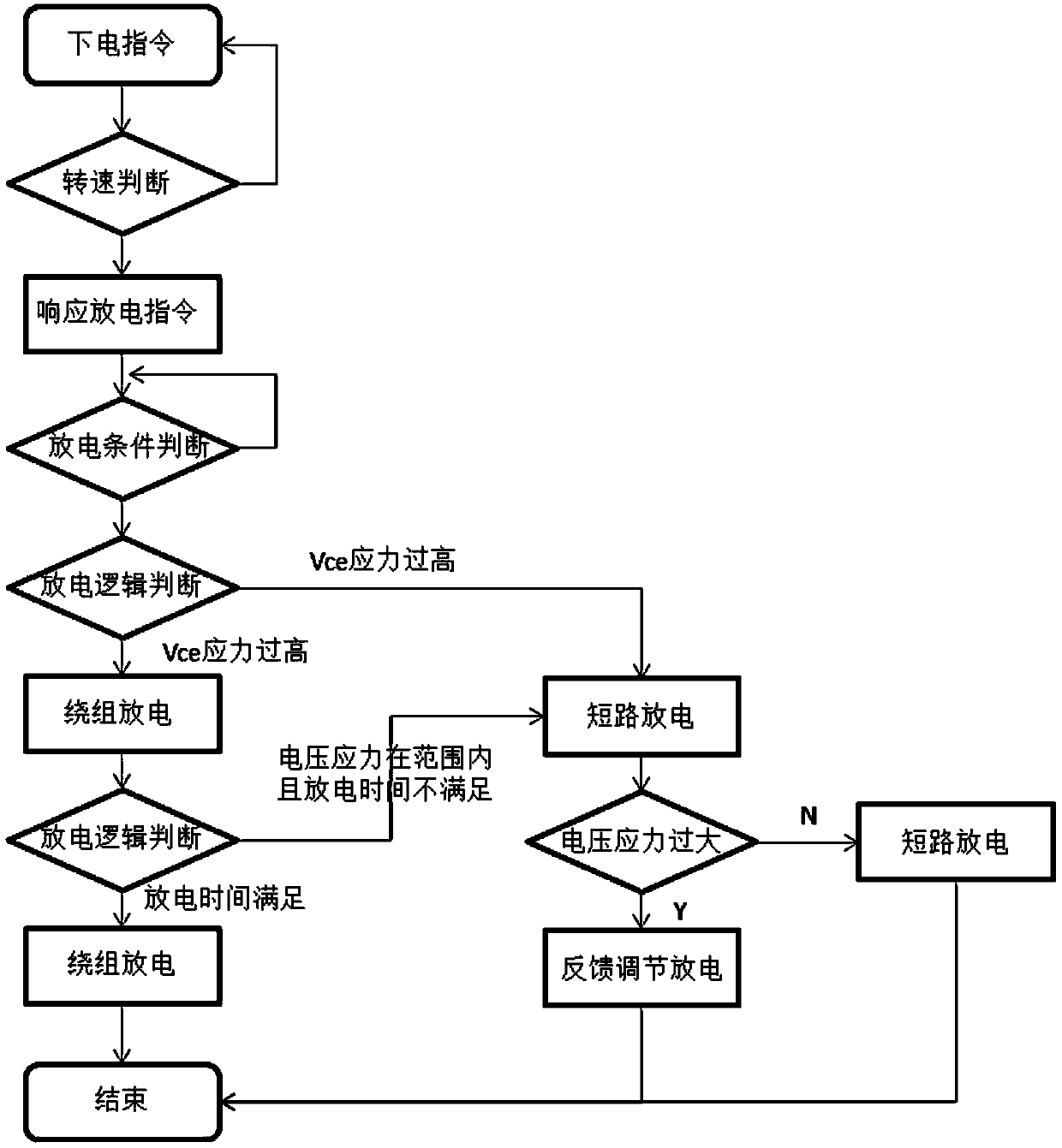
[0002] In order to ensure personal safety, the motor controller needs to have an active discharge function. The current active discharge technology mainly focuses on the following three discharge methods: 1. Discharge through the motor winding and add D-axis current. The discharge time is fast, but it will bring unexpected Torque affects the driving experience; 2. By adding an external discharge circuit, the risk is small and reliable, but it will increase the hardware cost; 3. The bridge wall is directly discharged, which is low in cost and fast in discharge speed, but the instantaneous current is large. Due to the high voltage circuit There is stray inductance on the ground, which leads to a large voltage stress when the IGBT (insulated gate bipolar transistor) is turned off. The test object is a 750V / 820A IGBT module. When the bus voltage is 520V, a single pulse short-circuit test is carried out, and the actual measurement of channel 3 The data Vce rushes to 716V, and as the bus voltage rises, the short-circuit current rises, the shutdown speed is accelerated, and the peak voltage will increase further until it exceeds the limit voltage of 750V
In actual working conditions, when the motor is running at high speed and the main relay of the power battery is disengaged, the film capacitor will be charged to the maximum back EMF by the motor feed. At this time, direct short-circuit discharge will cause damage to the IGBT. even breakdown

Method used


Image

  • Motor controller active discharge system and control method
  • Motor controller active discharge system and control method
  • Motor controller active discharge system and control method

Examples


Embodiment Construction

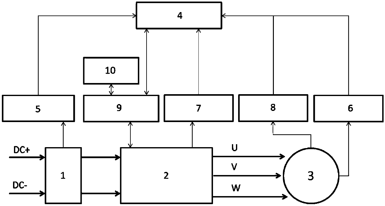
[0023] Such as figure 1 As shown, it is a motor controller active discharge system involved in this embodiment, including: input bus 1, IGBT circuit 2, drive unit 3, motor 4 and control unit 5, wherein: input bus 1, IGBT circuit 2, motor 3 and the control unit 5 are connected in series to form a loop, and the input end and the output end of the drive circuit 3 are respectively connected with the control unit 5 and the IGBT circuit 2 .

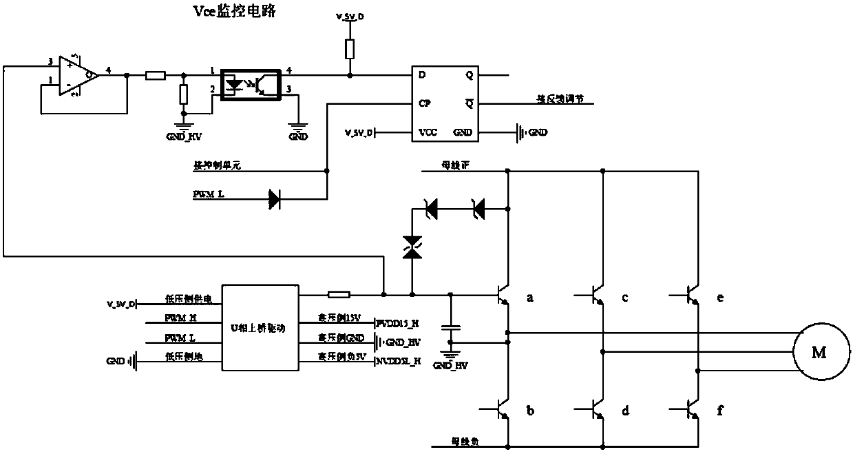
[0024] The IGBT circuit 2 is a three-phase bridge inverter circuit, comprising: three bridge arms 10 connected in parallel, each bridge arm 10 is connected in series with two IGBT single tubes a to f, wherein: three bridge arms 10 The central point of the U, V, and W terminals are respectively connected to the three-phase alternating current port of the motor 4.

[0025] The driving circuit includes: six sets of identical driving components, taking the U-phase upper bridge as an example, the input terminals of the driving chip are connected to...


PUM


Abstract

The invention discloses a motor controller active discharge system and a control method. The system comprises a film capacitor arranged on a bus, an IGBT circuit, a motor, an IGBT temperature samplingcircuit and a driving circuit which are connected with the IGBT circuit, a bus voltage sampling circuit connected with the film capacitor, and a motor temperature sampling circuit, a motor rotating speed sampling circuit and a driving circuit which are connected with the motor, wherein the driving circuit is with a power supply circuit. When the system finds that a motor winding or an IGBT modulegoes wrong, the system can select discharge paths respectively, the risk of active discharge IGBT failure is reduced, and a discharge speed problem is solved.

Description

technical field [0001] The invention relates to a technology in the field of motor drive control, in particular to an active discharge system and control method for a motor controller. Background technique [0002] In order to ensure personal safety, the motor controller needs to have an active discharge function. The current active discharge technology mainly focuses on the following three discharge methods: 1. Discharge through the motor winding and add D-axis current. The discharge time is fast, but it will bring unexpected Torque affects the driving experience; 2. By adding an external discharge circuit, the risk is small and reliable, but it will increase the hardware cost; 3. The bridge wall is directly discharged, which is low in cost and fast in discharge speed, but the instantaneous current is large. Due to the high voltage circuit There is stray inductance on the ground, which leads to a large voltage stress when the IGBT (insulated gate bipolar transistor) is turn...

Claims


Application Information

Patent Timeline
IPC IPC(8): H02P29/00
CPCH02P29/00
Inventor 黄鹏辉李育丁祥根
Owner SHANGHAI AUTOMOBILE GEAR WORKS
Learn More