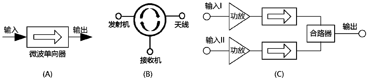
Microwave isolator

A unidirectional, microwave technology, applied in unidirectional transmission network, multi-terminal-to-network and other directions, can solve the problems of narrow frequency range, low reliability, complex structure, etc., achieve wide operating frequency range, meet development needs, volume small effect

Pending Publication Date: 2020-05-01
NO 43 INST OF CHINA ELECTRONICS TECH GRP CETC
View PDF0 Cites 0 Cited by
  • Summary
  • Abstract
  • Description
  • Claims
  • Application Information

AI Technical Summary

Problems solved by technology

[0015] A microwave one-way device proposed by the present invention can solve some problems existing in conventional ferrite microwave one-way devices, su

Method used


Image

  • Microwave isolator
  • Microwave isolator
  • Microwave isolator

Examples


Embodiment 1

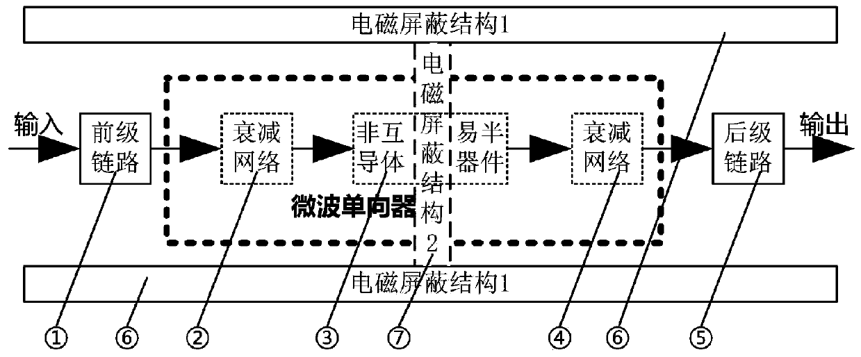
[0062] The structural design schematic diagram of embodiment 1 is shown in figure 1 . This embodiment is used to improve the reverse isolation from the output to the input in the radio frequency link without changing other link characteristic indexes.

[0063] In the figure ① is the pre-stage circuit in the radio frequency link; ② ④ is the optional attenuation network; ③ microwave amplifier circuit or operational amplifier circuit (including peripheral circuits); ⑤ is the post-stage circuit in the radio frequency link; The electromagnetic shielding structure on the side; ⑦ the electromagnetic shielding structure spanning the microwave one-way device.

[0064] Among them, the optional attenuation network shown in ②④ and the microwave amplifier circuit or operational amplifier circuit (including peripheral circuits) shown in ③ constitute the microwave one-way device in this structure.

[0065] Wherein, according to the operating frequency of the microwave one-way device, a mic...

Embodiment 2

[0070] The structural design schematic diagram of embodiment 2 sees figure 2 . This embodiment is used to improve the isolation from any output to input and between two output ports (output I and output II) without changing other link characteristics.

[0071] Compared with Embodiment 1, Embodiment 2 can only improve the one-way isolation from output to input; while Embodiment 2 can improve the one-way isolation from output to input, and can also improve the unidirectional isolation between the two output ports. Two-way isolation between.

[0072] Among them, ① shows the pre-stage link of the radio frequency link; ② shows the power divider; ③ shows the pre-stage attenuation network of two microwave one-way devices; Reciprocal semiconductor device; ⑤ shows the post-stage attenuation network of two microwave one-way devices; ⑥ shows the post-stage link of the radio frequency link; ⑦ shows the electromagnetic shielding structure on both sides of the radio frequency link; ⑧ sho...


PUM


Abstract

The invention provides a microwave isolator which can solve the technical problems that a conventional ferrite microwave isolator is complex in structure, large in size, low in reliability, narrow inuse frequency range and incapable of meeting requirements. The microwave isolator comprises a preceding-stage attenuation network, a non-reciprocal semiconductor device and a post-stage attenuation network, the preceding-stage attenuation network serves as an input stage of the isolator and is connected with the preceding-stage link; the post-stage attenuation network serves as an output stage ofthe isolator and is connected with the post-stage link; a radio frequency link formed from the input stage to the output stage is a transmission channel; electromagnetic shielding structures are arranged between the input/output ends of the non-reciprocal semiconductor device and on the two sides of a radio frequency link formed from the isolator input stage to the isolator output stage. A semiconductor device is adopted, the product working frequency range is wide, the relative bandwidth is also wide, and the application range is wider; the working frequency range of the microwave isolator isalmost not limited and can cover DC-terahertz, and as long as the semiconductor chip supports how high the working frequency, the semiconductor chip can be suitable for how high the frequency range.

Description

technical field [0001] The invention relates to the field of microwave circuit modules / components, in particular to a microwave one-way device. Background technique [0002] In the field of microwave circuit module / component technology, there is a non-reciprocal device or circuit (microwave one-way device for short) with microwave one-way transmission characteristics. Its basic characteristics are: figure 1 As shown in (A), there is only a small loss when transmitting microwave signals in the specified direction, but there is a large loss (isolation) when transmitting in other directions. [0003] Because of the unique characteristics of the microwave one-way device, it is widely used in various microwave circuit modules / components, subsystems, and complete machines to achieve such things as inter-stage isolation, crosstalk prevention, impedance matching, decoupling, transceiver Duplex function, so as to achieve the purpose of protecting the system and effectively improving...

Claims


Application Information

Patent Timeline
IPC IPC(8): H03H11/38
CPCH03H11/38
Inventor 周建政李莉刘认曾敏慧芮金城侯杨倪涛项玮
Owner NO 43 INST OF CHINA ELECTRONICS TECH GRP CETC
Why Eureka
Try Eureka