Radial compressor for charging device of internal combustion engine, charging device and lamellas for iris diaphragm mechanism, and method for producing lamella

A booster device and compressor technology, applied in the field of radial compressors, can solve problems such as low efficiency, achieve the effect of reducing costs and reducing the probability of failure

Active Publication Date: 2020-05-01
VITESCO TECH GERMANY GMBH
View PDF12 Cites 1 Cited by
  • Summary
  • Abstract
  • Description
  • Claims
  • Application Information

AI Technical Summary

Problems solved by technology

It is a significantly more advantageous but at the same time less efficient solution than the leading device and said variable cross-sectional reduction

Method used


Image

  • Radial compressor for charging device of internal combustion engine, charging device and lamellas for iris diaphragm mechanism, and method for producing lamella
  • Radial compressor for charging device of internal combustion engine, charging device and lamellas for iris diaphragm mechanism, and method for producing lamella
  • Radial compressor for charging device of internal combustion engine, charging device and lamellas for iris diaphragm mechanism, and method for producing lamella

Examples


Embodiment Construction

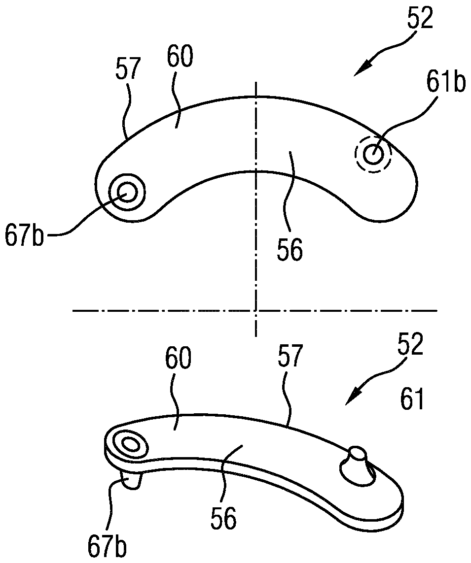
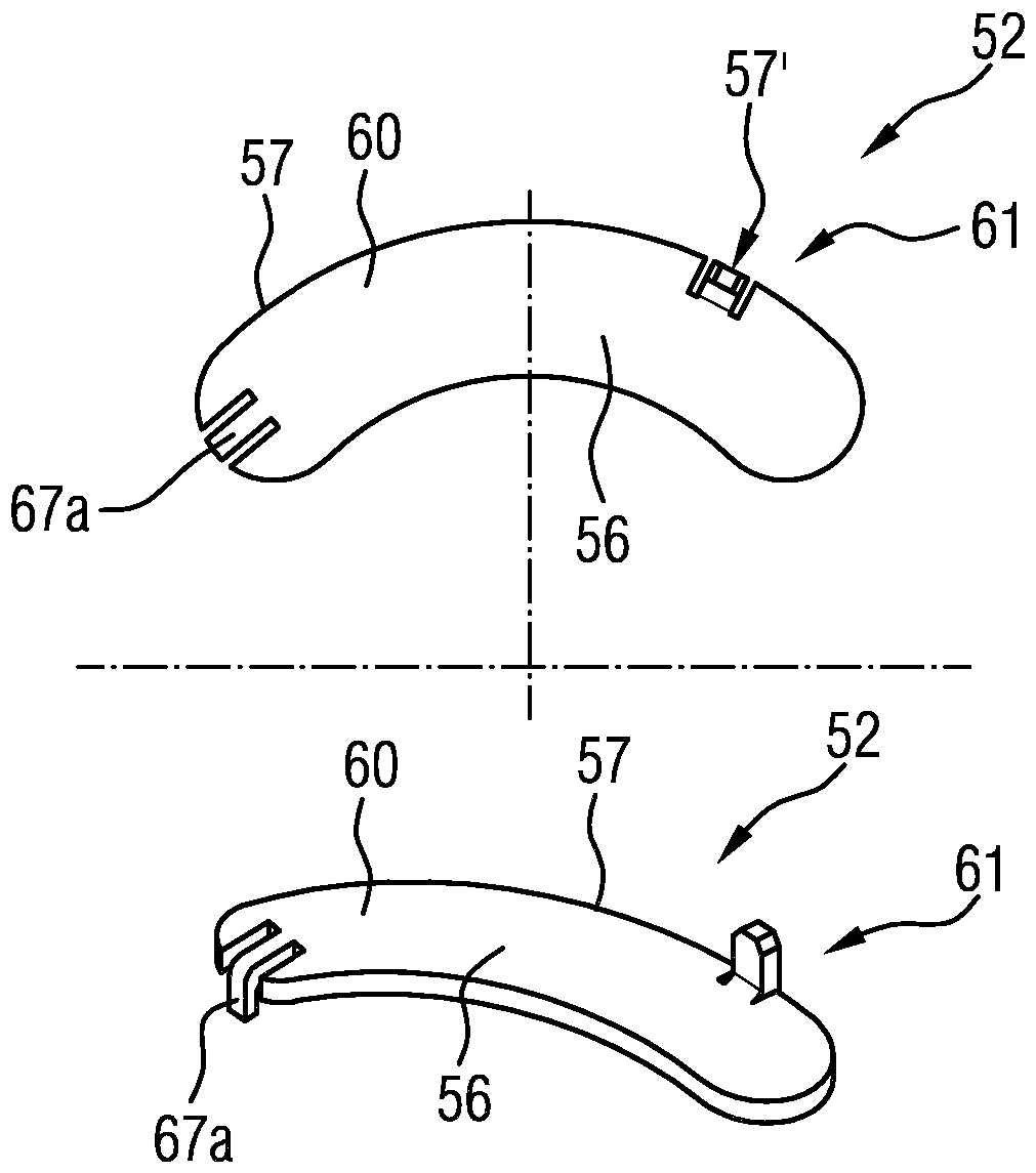
[0070] figure 1 A charging device for an internal combustion engine is shown schematically in section using an exhaust gas turbocharger 1 a according to the usual prior art, which comprises an exhaust gas turbine 20 , a radial compressor 30 and a rotor bearing 40 . The exhaust gas turbine 20 is equipped with a wastegate valve 29 and the exhaust gas mass flow AM is indicated by arrows. The radial compressor 30 has an overrun air recirculation valve 39 and the air mass flow LM is likewise indicated by an arrow. The so-called turbocharger rotor 10 of the exhaust gas turbocharger 1 a has a turbine wheel 12 , a compressor wheel 13 and a rotor shaft 14 (also called shaft for short). During operation, the turbocharger rotor 10 rotates about a rotor axis of rotation 15 of a rotor shaft 14 . The rotor axis of rotation 15 and simultaneously the turbocharger axis 2 (also called longitudinal axis) are indicated by the drawn center line and indicate the axial orientation of the exhaust g...


PUM


Abstract

The invention relates to a radial compressor (30) for a charging device of an internal combustion engine, for example a turbocharger. The radial compressor has a compressor wheel (13), which is arranged in a compressor housing (31) and is rotationally fixed to a rotatably mounted rotor shaft (14), and a fresh air supply channel (36) for conducting a fresh air mass flow rate (LM) to the compressorwheel (13) and paired with the compressor wheel. An iris diaphragm mechanism (50) is arranged at the upstream of the compressor wheel (13), the iris diaphragm mechanism is used to variably adjust a flow cross-section for the fresh air mass flow rate (LM) flowing against the compressor wheel (13). The iris diaphragm mechanism (50) additionally has multiple lamellas (52) each of which has a plate-shaped lamella main part (56) and a pin-shaped actuation element (61, 61a, 61b) as an integral component of the respective lamella (52). The invention additionally relates to the charging device (1) comprising the radial compressor (30) and the lamella (52) for the iris diaphragm mechanism (50) of the radial compressor (30) and to a method for producing the lamella (52).

Description

technical field [0001] The invention relates to a radial compressor for a charging device, in particular for charging an internal combustion engine with air at elevated pressure. The invention also relates to a charging device having such a radial compressor, a diaphragm mechanism for a radial compressor, and a method for producing such a diaphragm. Background technique [0002] Charging devices with radial compressors, in particular exhaust gas turbochargers, are increasingly used for power boosting in internal combustion engines of motor vehicles. This is happening more and more frequently with the aim of reducing the internal combustion engine in terms of construction size and weight with the same or even increased power and at the same time reducing consumption and thus lowering the CO 2 emission. Here, the operating principle of the exhaust gas turbocharger is to use the energy contained in the exhaust gas flow in order to increase the pressure in the intake system o...

Claims


Application Information

Patent Timeline
Patent Type & Authority Applications(China)
IPC IPC(8): F04D27/02F04D29/42F16K3/03
CPCF16K3/03F05D2220/40F05D2250/51F04D29/464F02B33/40F02B39/16F04D17/10F04D27/0253F04D29/4213F05B2250/02F05B2250/501
Inventor M.博格纳C.舍费尔S.斯拉维奇
Owner VITESCO TECH GERMANY GMBH
Why Eureka
Try Eureka