An automatic feeding system for bar material with lifting head
The technology of feeding system and lifting head is applied in the field of bar material feeding system with lifting head for active feeding, which can solve the problems of poor stirring uniformity, low success rate of nail suction, affecting the production rhythm of nail picking mechanism, etc. The effect of stability, high feeding efficiency and easy maintenance
- Summary
- Abstract
- Description
- Claims
- Application Information
AI Technical Summary
Problems solved by technology
Method used
Image
Examples
Embodiment 2
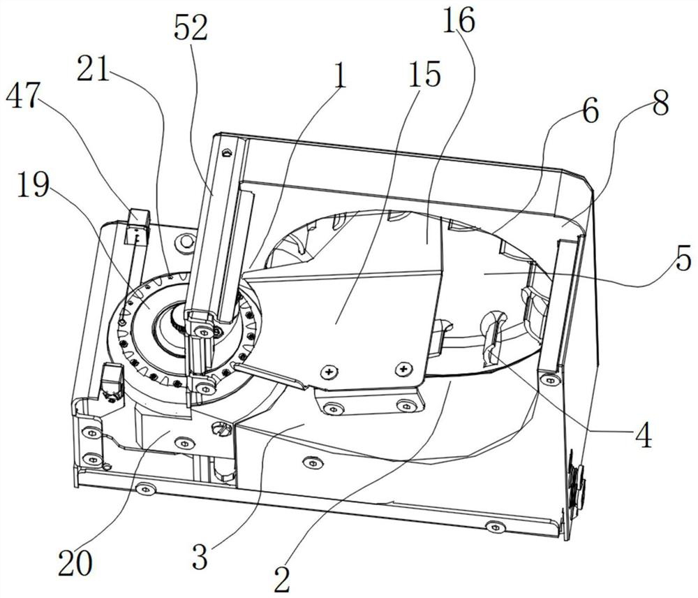
[0050] Such as Figure 6 As shown, on the basis of Embodiment 1, this embodiment provides a deformed structure of the hopper part. The collecting area 2 and the blanking area 1 are arranged along the axial direction of the collecting wheel, and the slope 3 is a cylindrical arc surface. At this time, the conveying mechanism is in the axial direction of the collecting wheel, and the hopper also includes a feeding slide 15, which is arranged from high to low along the collecting area 2 to the blanking area 1; one end of the feeding sliding plate 15 extends into the collecting wheel Wheel, the other end is arranged on the top of the blanking area 1, and the feeding slide 15 is provided with several chutes 18 along the blanking direction.
Embodiment 3
[0052] Such as Figure 7 to Figure 10As shown, on the basis of the above-mentioned embodiment 1 and embodiment 2, this embodiment provides a specific implementation structure of the second driving mechanism, the second driving mechanism includes a cardan shaft, a transmission shaft 23, a transmission wheel 24 and a driving motor (not shown in the figure), the output shaft 25 of the cardan shaft is connected to the mounting seat 20 through the rotation of the bearing 26, the bearing 26 is parallel to the turntable 19, the turntable 19 is connected to the output shaft 25 through the fixed shaft 27, and the input shaft 28 of the cardan shaft It is connected with the transmission shaft 23, the transmission wheel 24 is sleeved on the transmission shaft 23, and the transmission wheel 24 is connected with the driving motor; the transmission shaft 23 is rotationally connected with the mounting seat 20; a bushing 33 is arranged between the lower end of the transmission shaft 23 and the ...
Embodiment 4
[0055] Such as Figure 12 , Figure 13 As shown, on the basis of the above-mentioned embodiment 1 and embodiment 2, this embodiment provides a specific implementation structure of a second drive mechanism, the second drive mechanism includes a transmission wheel 24, a transmission shaft 23 and a drive motor 53, and the turntable 19 Be connected with transmission wheel 24 by fixed shaft 27, transmission wheel 24 is connected with transmission shaft 23, transmission shaft 23 is connected with driving motor by bevel gear 54, and described transmission shaft 23 is connected with mounting seat 20 rotation; Transmission wheel 24 is sheave, Transmission shaft 23 and the connected end of sheave are provided with dial and driving lever and are connected with sheave. It should be noted that, in order to coordinate the comparative relationship between the drawings of each embodiment when making the drawings, there are components with the same name in this embodiment and Embodiment 3. Fo...
PUM
 Abstract
Description
Claims
Application Information
 - R&D
- Intellectual Property
- Life Sciences
- Materials
- Tech Scout
- Unparalleled Data Quality
- Higher Quality Content
- 60% Fewer Hallucinations
Browse by: Latest US Patents, China's latest patents, Technical Efficacy Thesaurus, Application Domain, Technology Topic, Popular Technical Reports.
© 2025 PatSnap. All rights reserved.Legal|Privacy policy|Modern Slavery Act Transparency Statement|Sitemap|About US| Contact US: help@patsnap.com


