A vertical electroplating equipment

An electroplating equipment and vertical technology, applied in the field of vertical electroplating equipment, can solve the problems of increasing processing time, reducing processing efficiency, affecting electroplating efficiency and coating quality, etc., and achieving the effect of preventing clogging and improving electroplating efficiency.

Active Publication Date: 2021-07-16
江门市联益电镀科技有限公司
View PDF10 Cites 0 Cited by
  • Summary
  • Abstract
  • Description
  • Claims
  • Application Information

AI Technical Summary

Problems solved by technology

When the workpiece to be electroplated is very small, it may cause the wafer to leak out of the electroplating fixture, resulting in damage to the wafer, and the use of vibration to electroplate the wafer may lead to uneven electroplating of the wafer, which directly affects the overall electroplating efficiency and coating quality. Finally, when the parts need to be taken out, the parts need to be fished out, which is inconvenient to take out, increases the processing time and reduces the processing efficiency

Method used


Image

  • A vertical electroplating equipment
  • A vertical electroplating equipment
  • A vertical electroplating equipment

Examples


Embodiment 1

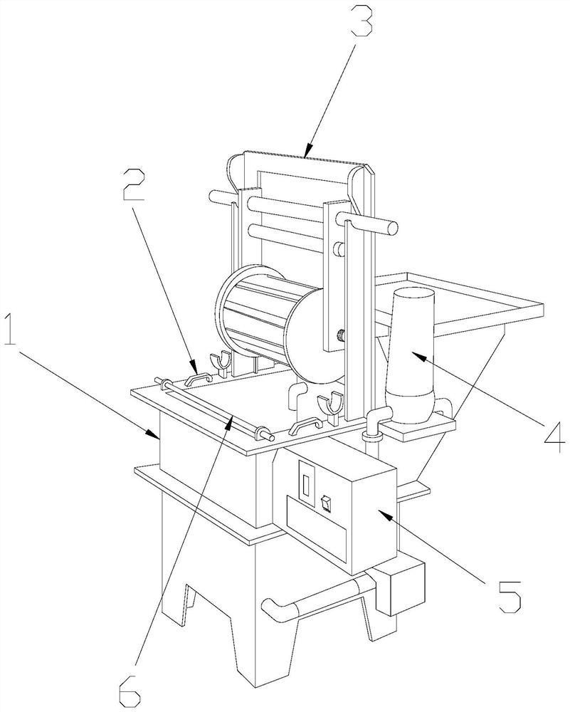
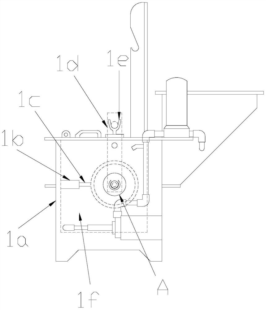
[0025] see Figure 1-Figure 4 , the present invention provides a kind of upright electroplating equipment, its structure comprises electroplating machine 1, lifting handle 2, drum filter support 3, filter 4, electric control box 5, anode rod 6, on the top of described electroplating machine 1 A drum filter support 3 is provided, and the electroplating machine 1 is glued to the drum filter support 3. An anode rod 6 is arranged on the top surface of the electroplater 1, and the electroplater 1 and the anode rod 6 connected, a handle 2 is provided between the anode rod 6 and the drum filter support 3, the handle 2 is fixedly connected with the electroplating machine 1, and the surface of the electroplating machine 1 is provided with a filter 4 , the electroplating machine 1 is connected with the filter 4, the electric control box 5 is installed on the surface of the electroplating machine 1, and the electroplating machine 1 is composed of an upright chassis 1a, a movable mounting...

Embodiment 2

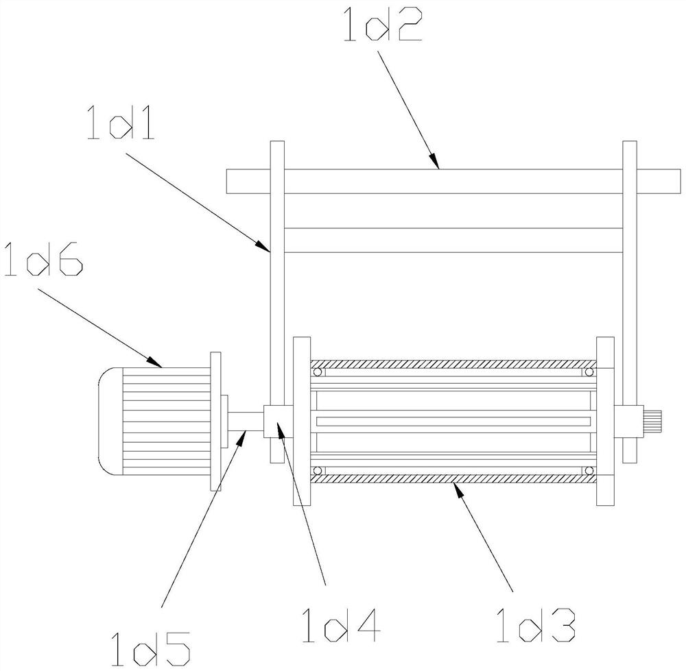
[0031] see Figure 1-Figure 6 , the present invention provides a kind of upright electroplating equipment, described sweeping mechanism 1d36 is made up of rotating shaft g1, gear g2, sweeping brush g3, fixed shaft g4, described rotating shaft g1 is provided with gear g2 on the right end, described The rotating shaft g1 and the gear g2 are fixedly connected, the left end of the rotating shaft g1 is provided with a fixed shaft g4, the rotating shaft g1 and the fixed shaft g4 are an integrated structure, and the rotating shaft g1 is equidistantly distributed on the surface There are four leveling brushes g3, and the rotating shaft g1 is connected with the leveling brushes g3.

[0032] The surface of the gear g2 is provided with a positioning U-shaped bar g21, and the gear g2 is movably connected with the positioning U-shaped bar g21.

[0033] The cleaning brush 1c is connected with the filter inner barrel 1d33 through the filter screen 1d34, and is used to clean the filter scree...


PUM


Abstract

The invention discloses a vertical electroplating equipment, the structure of which comprises an electroplating machine, a lifting handle, a drum filter support, a filter, an electric control box, and an anode rod. The electroplating machine consists of an upright chassis, a movable mounting frame, a cleaning brush, The electroplating machine is composed of electroplating device, cathode copper fork, and electroplating tank. The electroplating machine uses the motor to drive the electroplating drum to rotate through the motor shaft, and the electroplating drum can neatly bind small workpieces on its inner wall through the hardware accessories inserts to prevent the workpiece from being electroplated. Leakage from the fixture causes damage to the workpiece. The filter inner barrel filters the electroplating solution through the filter under the hardware fitting insert and penetrates into the surface of the workpiece, which improves the electroplating efficiency. The electroplating drum uses the sweeping mechanism to clean the workpiece in the hardware fitting insert Perform sweeping electroplating to improve the quality of the electroplating layer of the workpiece.

Description

technical field [0001] The invention relates to the field of metal electroplating, in particular to a vertical electroplating equipment. Background technique [0002] Electroplating is the process of plating a thin layer of other metals or alloys on some metal surfaces by using the principle of electrolysis. According to the actual needs of electroplating, different electroplating solutions and electroplating equipment will be selected. Vertical electroplating equipment is one of the commonly used electroplating equipment. It is mainly used for electroplating operations of wafers. When the workpiece to be electroplated is very small, it may cause the wafer to leak out of the electroplating fixture, resulting in damage to the wafer, and the use of vibration to electroplate the wafer may lead to uneven electroplating of the wafer, which directly affects the overall electroplating efficiency and coating quality. Finally, when the parts need to be taken out, the parts need to b...

Claims


Application Information

Patent Timeline
Patent Type & Authority Patents(China)
IPC IPC(8): C25D17/20
CPCC25D17/20
Inventor 姜志写
Owner 江门市联益电镀科技有限公司
Why Eureka
Try Eureka